ML21109A123
| ML21109A123 | |
| Person / Time | |
|---|---|
| Issue date: | 05/31/2021 |
| From: | Cronise L, Matthew Gordon, Raj Iyengar, Marsden B, Srinivasan M, Turk R, Von-Lensa W Office of Nuclear Regulatory Research, Numark Associates |
| To: | |
| Matthew Gordon | |
| References | |
| NRC-HQ-25-14-E-0004 TLR-RES/DE/CIB-2021-07 | |
| Download: ML21109A123 (208) | |
Text
TLR/RES/DE/CIB-2021-07 Additional Technical Information in Support of the U.S. Nuclear Regulatory Commission Review of the 2017 Edition of ASME Code,Section III, Division 5, High Temperature Reactors, Subsection HH, Class A Nonmetallic Core Support Structures," Subpart A, Graphite Materials May 2021 PREPARED FOR:
U.S. NUCLEAR REGULATORY COMMISSION CONTRACT NO. NRC-HQ-25-14-E-0004 TASK ORDER NO. 31310018F019 PREPARED BY:
NUMARK Associates, Inc.
Makuteswara Srinivasan, Barry Marsden, Werner von Lensa, Lauren Cronise, Rick Turk PROJECT MANAGERS:
Office of Nuclear Regulatory Research, U.S. Nuclear Regulatory Commission Matthew Gordon, Raj Iyengar
DISCLAIMER This report was prepared as an account of work sponsored by an agency of the U.S. Government. Neither the U.S. Government, nor any agency thereof, nor any employee, makes any warranty, expressed or implied, or assumes any legal liability or responsibility for any third partys use, or the results of such use, of any information, apparatus, product, or process disclosed in this publication, or represents that its use by such third party complies with applicable law.
ii
This report does not contain or imply legally binding requirements, nor does it establish or modify any regulatory guidance or positions of the U.S. Nuclear Regulatory Commission, and it is not binding on the Commission.
iii
ACRONYMS AND ABBREVIATIONS ADAMS Agencywide Documents Access and Management System AGR Advanced Gas-Cooled Reactor ASME American Society of Mechanical Engineers ASTM American Society for Testing and Materials AVR Arbeitsgemeinschaft Versuchsreaktor BPVC Boiler and Pressure Vessel Code C Celsius CTE coefficient of thermal expansion DDN design data need DS design specification(s)
F Fahrenheit FEA finite element analysis FEM finite element model(ing)
GCA graphite core assembly GCC graphite core component HTGR high-temperature gas-cooled reactor HTR high-temperature reactor HTTR high-temperature test reactor ISI inservice inspection KTA Kerntechnischer Ausschuss Magnox magnesium nonoxidizing (reactor)
MDS material data sheet MTR material test reactor NGNP Next Generation Nuclear Plant NQA Nuclear Quality Assurance NRC U.S. Nuclear Regulatory Commission NUMARK NUMARK Associates, Inc.
OE operating experience PBMR pebble bed modular reactor PBR pebble bed reactor PIE postirradiation examination PIRT phenomena identification and ranking table POF probability of failure RAI request for additional information iv
Sg design equivalent stress SRC structural reliability class THTR Thorium High-Temperature Reactor TLR technical letter report WEC Westinghouse Electric Company v
This page is left blank intentionally vi
EXECUTIVE
SUMMARY
This technical letter report (TLR) is a companion report to TLR/RES/DE/CIB-2020-10, Technical Input for the U.S. Nuclear Regulatory Commission Review of the 2017 Edition of ASME Boiler and Pressure Vessel Code,Section III, Division 5, High Temperature Reactors:
Subsection HH, Class A Nonmetallic Core Support Structures, Subpart A, Graphite Materials, issued December 2020 (Agencywide Documents Access and Management System (ADAMS)
Accession No. ML20344A001).
This TLR contains commentary and review guidance on Subsection HH, Subpart A, that were generated during the assessment by NUMARK Associates, Inc. (NUMARK), discusses potential items for consideration in the American Society of Mechanical Engineers (ASME) Boiler and Pressure Vessel Code (BPVC) for graphite component design, highlights specific experimental data needs that may be challenging for both designers and U.S. Nuclear Regulatory Commission (NRC) reviewers, and provides supplemental information that was used in the bases for the recommendations made in TLR/RES/DE/CIB-2020-10.
This TLR documents several items for additional consideration that could affect the use of Subsection HH, Subpart A, or of other sections of the ASME BPVC for the design of graphite core components, as well as the NRC staffs review of the associated design documents. The most significant of these, identified as items for additional consideration in TLR/RES/DE/CIB-2020-10 and expanded upon in this TLR, are design requirements for (1) surveillance coupons, (2) disassembly and reassembly of graphite core components (GCCs), (3) allowable probability of failure for notched and radiused areas, and (4) graphite damage tolerance. These topics should be considered for incorporation into Subsection HH, Subpart A, or other sections of the ASME BPVC, because of the unique properties of graphite relative to traditional metallic and metal alloy materials used in light-water-cooled reactors.
NUMARKs assessment of Subsection HH, Subpart A, identified two principal additional data needs that may confront graphite component designers and NRC technical reviewers. The first concerns the graphite fatigue limit, which Subsection HH, Subpart A, identifies as under preparation. The second concerns data in support of the damage tolerance requirements of Subsection HH, Subpart A. Such data are crucial to establishing component condition monitoring protocols and executing aging management programs to assess progressive or ongoing degradation of graphite components. They are also necessary for setting suitable safe operational life limits for replaceable components and for developing safety cases to support continued operation until the subsequent shutdown.
In addition to these principal needs, the need for several other types of data emerged, including the following:
(1) more reliable graphite creep data vii
(2) comprehensive understanding of, and models that appropriately incorporate, the interactive effects of graphite damage on the subsequent behavior of graphite under reactor operational conditions of load, temperature, and coolant environment (3) buckling strength data as a function of geometry (length-to-diameter or equivalent dimension) for nonirradiated, irradiated, and irradiated and oxidized conditions (4) the graphite fatigue limit, which Subsection HH, Subpart A, describes as under preparation (5) data to support damage tolerance requirements in Subsection HH, Subpart A The appendices to this TLR provide supplemental information used to make the recommendations in TLR/RES/DE/CIB-2020-10. Appendix A, A Discussion of the Various (Structural) Design Codes and Design Practices Used for High-Temperature Reactors with Graphite Moderators and Reflectors, documents how other structural design codes and design practices used for gas-cooled reactors with graphite moderators and reflectors were reviewed and compared to Subsection HH, Subpart A, to make technical recommendations. Appendix B, On Establishing Temperature and Stress Limits, briefly discusses factors for establishing temperature and stress limits, a critical part of Subsection HH, Subpart A. Appendix C, Graphite Damage Tolerance Operating Experience in Previous Gas-Cooled Reactors, reviews the operating experience of graphite-moderated gas-cooled reactors that supported NUMARKs recommendations in TLR/RES/DE/CIB-2020-10. Appendix C highlights the importance of clearly defining graphite damage tolerance, a topic that NUMARK recommended for NRC staff review in TLR/RES/DE/CIB-2020-10. Appendix D, Reconciliation of NRC Graphite Phenomena Identification and Ranking Tables with Industry Design Data Needs as Related to the Requirements of the American Society of Mechanical Engineers Boiler and Pressure Vessel Code,Section III, Division 5, High Temperature Reactors, Subsection HH, Class A Nonmetallic Core Support Structures, Subpart A, Graphite Materials, documents NUMARKs review of NUREG/CR-6944, Next Generation Nuclear Plant Phenomena Identification and Ranking Tables (PIRTs), Volume 5, Graphite PIRTs, issued March 2008 (ADAMS Accession No. ML081140463). This review noted how Subsection HH, Subpart A, addressed issues raised in NUREG/CR/6944; it informed NUMARKs assessment of Subsection HH, Subpart A.
Recommendations made by NUMARK in this TLR on Subsection HH, Subpart A, are not NRC-endorsed positions.
viii
CONTENTS
- 1. Introduction ............................................................................................................................ 1 Background ....................................................................................................................... 1 Report Organization .......................................................................................................... 1
- 2. Additional Commentary on the Technical Evaluation of Subsection HH, Subpart A, and Potential Guidance for Designers and Reviewers ................................................................. 2 Article HHA-1000: Introduction ......................................................................................... 2
2.1.1 HHA-1230
Design ................................................................................................. 2
2.1.2 HHA-1410
Boundary between Graphite Core Components and Core Support Structures .............................................................................................................. 3
2.1.3 HHA-1420
Boundary between Graphite Core Components and Fuel Pebbles or Compacts .............................................................................................................. 3 2.1.4 Figure HHA-1400-2: Jurisdictional Boundary for Graphite Core Components and AssembliesLongitudinal Section View ............................................................... 4 Article HHA-2000: Materials ............................................................................................. 5
2.2.1 HHA-2130
Deterioration of Materials During Service ............................................ 5
2.2.2 HHA-2220
Irradiated Material Properties .............................................................. 5
2.2.3 HHA-2230
Oxidized Material Properties ............................................................... 6 Article HHA-3000: Design ................................................................................................ 6
2.3.1 HHA-3100
General Design .................................................................................... 6
2.3.2 HHA-3112
Enveloping Graphite Core Components .............................................. 7
2.3.3 HHA-3122
Loadings .............................................................................................. 7 2.3.4 HHA-3123.1: Design Fast Flux Distribution ............................................................ 8 2.3.5 HHA-3123.2: Design Temperature Distribution ...................................................... 8 2.3.6 HHA-3223.3: Design Mechanical Load .................................................................. 9
2.3.7 HHA-3141
Oxidation ........................................................................................... 10 2.3.8 HHA-3142.3: Internal Stresses Due to Irradiation ................................................ 10
2.3.9 HHA-3143
Abrasion and Erosion ........................................................................ 11 2.3.10 HHA-3144: Graphite Fatigue .............................................................................. 11 2.3.11 HHA-3145: Compressive Loading ...................................................................... 12 2.3.12 HHA-3212: General Design Requirements for the Graphite Core Components 12 2.3.13 HHA-3215.1: General ......................................................................................... 12 2.3.14 HHA-3216: Derivation of Equivalent Stress........................................................ 12 2.3.15 HHA-3217: Calculation of Probability of Failure ................................................. 12 ix
2.3.16 HHA-3220: Stress Limits for Graphite Core ComponentsSimplified Assessment ......................................................................................................... 13 2.3.17 HHA-3221: Design Limits ................................................................................... 14 2.3.18 HHA-3222.3: Deformation Limits ........................................................................ 14 2.3.19 HHA-3233: Level B Service Limits ..................................................................... 14 2.3.20 HHA-3240: Experimental LimitsDesign-by-Test ............................................. 14 2.3.21 HHA-3243: Experimental Proof of Strength, Service Load Rating ..................... 15 2.3.22 HHA-3323: General Design Rules...................................................................... 15 2.3.23 HHA-3330: Design of the Graphite Core Assembly ........................................... 15 Article HHA-4000: Machining, Examination, and Testing............................................... 16
2.4.1 HHA-4212
Nondestructive Examination Procedures .......................................... 16
2.4.2 HHA-4232
Dimensional Examination .................................................................. 16 2.4.3 HHA-4233.5: Repair of Defects and Flaws .......................................................... 16
2.4.4 HHA-4243
Posttest Examination of Graphite Core Components ........................ 16 Article HHA-5000: Installation and Examination ............................................................ 17
2.5.1 HHA-5000
Installation and Examination .............................................................. 17
2.5.2 HHA-5223
Qualifications of Examination Personnel ........................................... 17
2.5.3 HHA-5311
Construction Procedures ................................................................... 18
2.5.4 HHA-5500
Examination Postinstallation .............................................................. 18 Article HHA-8000: Nameplates, Stamping, and Reports................................................ 19 Mandatory Appendix HHA-I: Graphite Material Specifications ....................................... 19 Mandatory Appendix HHA-II: Requirements for Preparation of a Material Data Sheet.. 19
2.8.1 HHA-II-1000
Introduction ..................................................................................... 19
2.8.2 HHA-II-2000
Material Data Sheet Forms, Forms MDS-1 and MDS-2 ................. 20 2.8.3 Table HHA-II-2000-1: Notes on Material Data Sheet, Forms MDS-1 and MDS-2 21
2.8.4 HHA-II-3000
Detailed Requirements for Derivation of the Material Data Sheet As-Manufactured Properties ................................................................................ 22
2.8.5 HHA-II-3100
Material Reliability Curve Parameters (Two Parameter for Simple Assessment) ........................................................................................................ 23
2.8.6 HHA-II-4000
Detailed Requirements for Derivation of the Material Data Sheet Irradiated Properties ............................................................................................ 23 Mandatory Appendix HHA-III: Requirements for Generation of Design Data for Graphite Grades ............................................................................................................................ 24
2.9.1 HHA-III-3000
Properties To Be Determined ........................................................ 24 x
2.9.2 HHA-III-3100
As-Manufactured Graphite ............................................................ 24
2.9.3 HHA-III-3300
Irradiated Graphite ........................................................................ 25
2.9.4 HHA-III-4000
Requirement for Representative Data ........................................... 25
2.9.5 HHA-III-5000
Use of Historical Data .................................................................... 25 Nonmandatory Appendix HHA-A: Graphite as a Structural Material ........................... 25 2.10.1 HHA-A-1000: Introduction .................................................................................. 25 2.10.2 Figure HHA-A-1100-1 .......................................................................................... 26 2.10.3 HHA-A-1120: Mixing and Forming...................................................................... 26 2.10.4 HHA-A-1130: Baking and Impregnation ............................................................. 26 Nonmandatory Appendix HHA-B: Environmental Effects in Graphite ......................... 26 2.11.1 HHA-B-4000: Salt Coolant-Graphite Interactions ............................................... 26 Nonmandatory Appendix HHA-D: Guidance on Defects and Flaws in Graphite ......... 26
- 3. Items for Additional Consideration in Subsection HH, Subpart A; Graphite Design Data; and Core Inspection Technology ................................................................................................ 27 Items for Additional Consideration in Subsection HH, Subpart A.................................... 27 3.2.1 Incorporation of Detailed Inspection Requirements in Design .............................. 27 3.2.2 Inspection Requirements ....................................................................................... 27 3.2.3 Design Requirement for Surveillance Coupons .................................................... 28 3.2.4 Incorporation of Requirements for Repair and Replacement in Design ................ 28 3.2.5 Design Requirement for Disassembly and Reassembly of Graphite Core Components ........................................................................................................ 29 3.2.6 Design Requirement for Allowable Probability of Failure for Notches and Radiused Areas ................................................................................................................... 29 3.2.7 Design Requirement for Graphite Damage Tolerance .......................................... 30 3.2.8 Special Design Requirements for Anchor Graphites ............................................. 30 3.2.9 Requirements for Functionality of the Graphite Core Components and Graphite Core Assembly .................................................................................................... 30 3.2.10 Requirements for Allowable Component Deformation ........................................ 30 3.2.11 Requirements for Emissivity ................................................................................ 31 3.2.12 Requirements for Permeability ............................................................................ 32 3.2.13 Specific Requirements for Seismic Events .......................................................... 32 3.2.14 Requirements for Incorporation of Disposal in Design ........................................ 32 Items for Additional Consideration in Graphite Design Data ........................................... 32 3.3.1 Cyclic Fatigue Limits ............................................................................................. 32 xi
3.3.2 Damage Tolerance Limits ..................................................................................... 33 3.3.3 Irradiation Creep .................................................................................................... 34 3.3.4 Irradiation-Induced Change in the Coefficient of Thermal Expansion, Including the Effects of Creep Strain ........................................................................................ 35 3.3.5 Irradiation-Induced Changes in Mechanical Properties (Strength, Toughness),
Including the Effects of Creep Strain (Stress) ..................................................... 36 3.3.6 Buckling Strength .................................................................................................. 36 3.3.7 Tribological Properties ........................................................................................... 36 3.3.8 Changes in Graphite Pore Structure ..................................................................... 37 3.3.9 Comprehensive Models ......................................................................................... 37 Items for Additional Consideration in Graphite Core Inspection Technology .................. 37
- 4. Summary ............................................................................................................................. 38
- 5. References .......................................................................................................................... 40 Appendix A: A Discussion of the Various (Structural) Design Codes and Design Practices Used for High-Temperature Reactors with Graphite Moderators and Reflectors ............................... A-1 Appendix B: On Establishing Temperature and Stress Limits ................................................. B-1 Appendix C: Graphite Damage Tolerance Operating Experience in Previous Gas-Cooled Reactors.................................................................................................................................... C-1 Appendix D: Reconciliation of the NRC Graphite Phenomena Identification and Ranking Tables with Industry Design Data Needs as Related to the Requirements of the American Society of Mechanical Engineers Boiler and Pressure Vessel Code,Section III, Division 5, High Temperature Reactors, Subsection HH, Class A Nonmetallic Core Support Structures, Subpart A, Graphite Materials ............................................................................................... D-1 xii
- 1. Introduction
Background
The absence of a code of construction endorsed by the U.S. Nuclear Regulatory Commission (NRC) for nuclear reactors operating above 425 degrees Celsius (C) (800 degrees Fahrenheit (F)) is a significant obstacle for advanced nonlight-water reactor designs. The review and approval of an elevated-temperature code of construction during the licensing review of a new nuclear power plant would entail substantial cost and a longer schedule.
In a letter dated June 21, 2018 (Agencywide Documents Access and Management System (ADAMS) Accession No. ML18184A065), the American Society of Mechanical Engineers (ASME), based on letters from both industry consortia and individual companies interested in developing advanced nonlight-water reactor designs, asked the NRC to review and endorse the 2017 Edition of the ASME Boiler and Pressure Vessel Code (BPVC),Section III, Rules for Construction of Nuclear Facility Components, Division 5, High Temperature Reactors. The NRC responded in a letter dated August 16, 2018 (ADAMS Accession No. ML18211A571), that the agency was initiating efforts to endorse (with conditions, if necessary) the 2017 Edition of ASME BPVC,Section III, Division 5, in a new regulatory guide, as one way of meeting the NRCs regulatory requirements.
To support the review and endorsement effort, the NRC requested the technical support of NUMARK Associates, Inc (NUMARK). In response, NUMARK authored the technical letter report (TLR) TLR/RES/DE/CIB-2020-10, Technical Input for the U.S. Nuclear Regulatory Commission Review of the 2017 Edition of ASME Boiler and Pressure Vessel Code,Section III, Division 5, High Temperature Reactors: Subsection HH, Class A Nonmetallic Core Support Structures, Subpart A, Graphite Materials, issued December 2020 (ADAMS Accession No. ML20344A001). During its assessment, NUMARK drafted commentary and review guidance on Subsection HH, Subpart A; identified items for additional consideration related to graphite component design requirements; and documented specific experimental data needs that may be challenging for both designers and NRC reviewers. This companion report documents NUMARKs observations and provides additional background information supporting the bases for the recommendations made in TLR/RES/DE/CIB-2020-10.
Report Organization While Section 1 is introductory in nature, Section 2 of this report contains additional commentary and guidance on Subsection HH, Subpart A, which are recommended for NRC reviewers.
Section 3 of this report describes several items for consideration in Subsection HH, Subpart A, that should be addressed either in Subsection HH, Subpart A, or elsewhere in the ASME BPVC.
Some of these items concern the structural integrity of the graphite core components (GCCs) and the graphite core assembly (GCA), while others are not directly related to structural issues.
Future ASME Code Cases or users may address these items specifically for their particular designs. Section 3 also identifies challenges for designers in graphite design data that may be needed for Subsection HH, Subpart A. Although Subsection HH, Subpart A, does not address specific nondestructive examination and evaluation methods and procedures in detail, Section 3 of this report does consider these topics, with reference to previous practices from operating 1
experience (OE) of gas-cooled reactors. Inservice component condition monitoring and periodic reassessment and confirmation of the design assumptions are cornerstones of defense in depth, ensuring component function and safe reactor operation. This is especially important for new reactor designs with few, if any, operational data confirming the robustness of the design assumptions used for graphite components.
Section 4 of this report summarizes NUMARKs assessment of Subsection HH, Subpart A.
Four appendices follow, which provide technical background information used in the assessment.
Recommendations made by NUMARK in this TLR on Subsection HH, Subpart A, are not NRC-endorsed positions.
- 2. Additional Commentary on the Technical Evaluation of Subsection HH, Subpart A, and Potential Guidance for Designers and Reviewers Article HHA-1000: Introduction
2.1.1 HHA-1230
Design This subsubarticle summarizes aspects of the design of GCCs and GCAs covered in HHA-3000, including the following:
- within-billet and billet-to-billet variability in material properties
- effects of fast neutron irradiation, irradiation temperature, and oxidation on the appropriate mechanical and thermal properties and on dimensional change behavior, as well as the design and service loadings
- use of probabilistic and deterministic design methodologies
- fast-neutron-irradiation-induced changes in component geometries, which could significantly affect GCA stability and geometry (and these in turn could affect the coolant flowpaths, the freedom of movement of fuel and control devices, and the interaction with interfacing metallic components or structures)
The incorporation of billet-to-billet and within-billet property variation is also considered in the American Society for Testing and Materials (ASTM) standards ASTM D7219-08, Standard Specification for Isotropic and Near-Isotropic Nuclear Graphites, and ASTM D7301-08, Standard Specification for Nuclear Graphite Suitable for Components Subjected to Low Neutron Irradiation Dose. The use of deterministic methodology in these standards is notable.
When there is large uncertainty in the data, the designer may need to use appropriate deterministic methodology to support the design assumptions.
This subsubarticle considers potential geometry changes of the GCA due to irradiation.
However, it largely leaves to the designer the question of how to account for such changes. An 2
important element to consider is the requirement for monitoring degradation using trepanned and surveillance coupons. Testing of irradiated coupons in the actual reactor and postirradiation examination (PIE) of relevant properties are important for confirming material test reactor (MTR) data used to design GCCs.
2.1.2 HHA-1410
Boundary between Graphite Core Components and Core Support Structures This general subsubarticle defines the boundaries of jurisdiction, according to the definitions in Figures HHA-1400-1 and HHA-1400-2. The technical reviewer may need to check how the user defines the boundaries in the design.
HHA-1410(a) states that the boundary includes the interface with metallic/ceramic core restraints. For example, if the graphite surface is oxidized, then gaseous oxidation products may be expected to react with the adjacent metallic material, if any. Additionally, if the metallic materials oxidize, chemical reactions could occur between the oxide products of the metallic materials at reactor operating temperature. If the temperature is sufficient for the oxide to be in liquid form, especially if the oxide contains impurities, it could stick to graphite because of adhesive bonding. Thus, the technical reviewer should confirm that the user considers such possible effects on graphite and the metallic restraints. So far, consideration of such interactions seems to have been beyond the scope of Subsection HH, Subpart A, as the latter addresses solely GCCs and so accounts only for the oxidation of graphite, not for the environmental effects of interfacing materials at the boundary.
The technical reviewer should confirm that the user incorporates into the design the differential thermal expansion at the boundary between steel and graphite; this applies to both HHA-1410(a) and HHA-1410(b).
2.1.3 HHA-1420
Boundary between Graphite Core Components and Fuel Pebbles or Compacts Although this subsubarticle is related to defining the boundaries of jurisdiction, a detailed technical assessment of the design should also consider the aspects discussed below.
As stated in HHA-1420(a), fuel pebbles and compacts may bear on or be constrained by GCCs.
The NRC staff raised this issue in Requests for Additional Information (RAIs) 1.2.24 and 1.2.25 in response to a proposed pebble bed modular reactor (PBMR) design by Exelon Corporation (NRC, 2002).
Self-loadings by pebbles and compacts and GCC constraints on them have occurred in the Arbeitsgemeinschaft Versuchsreaktor (AVR) and the Thorium High-Temperature Reactor (THTR) (Ziermann and Ivens, 1997). Interactions between fuel pebbles and the graphite core generated graphite dust that could carry radionuclides (Moormann, 2008a, 2008b; Beck and Pincock, 2011; Humrickhouse, 2011). Also, fuel pebbles, debris from the pebbles, and broken parts got stuck at the bottom reflector and fuel discharge components, constraining their free movement (Wahlen et al., 2000). Subarticle 3000, Design, does not cover these aspects adequately.
3
In a pebble bed reactor (PBR), frictional wear between the fuel pebbles and the graphite core is a consideration. Fuel pebble graphite is not really graphite, in that it has not experienced graphitization temperatures but has only been heat treated; it is essentially baked carbon (pyrolysis conversion). It is therefore expected to be harder than the softer graphite core (which has been graphitized). Rubbing of the harder surface against the softer surface would cause graphite component wear, forming graphite dust. The design of the GCC assembly structure should consider information on such erosion-corrosion (the rougher graphite surface may be more prone to oxidation corrosion than the smooth surface).
Also, the potential contraction and expansion of fuel compacts in the (graphite) fuel rods and the shrinkage of the fuel rods may affect the fuel rod geometry, which could influence the process of unloading and reloading fuel.
Graphite dust can also be produced from contact and movement of pebbles or from movement of graphite blocks due to temperature gradients, coolant flow, or vibrations. Because of nonuniform temperature distribution and stress and deformation from irradiation, there is movement within the graphite reflector block assembly, which can lead to wear and create graphite dust and small particles. In response to a presentation by Exelon on a proposed PBMR design on graphite, the NRC staff raised a concern in RAI 1.2.26 that graphite dust might be deposited and agglomerate on piping, clogging the flow of helium (NRC, 2002).
RAI 1.2.25 addressed the effect of erosion due to dust formation on the structural integrity of the graphite (NRC, 2002).
Dust particles can collect at the bottom of the core or be carried off and collect on surfaces in the primary circuit, including the heat exchanger, decreasing its efficiency. Dust or particles collecting at the bottom of the core could hinder complete movement of the fuel or the control rod (Beck and Pincock, 2011).
2.1.4 Figure HHA-1400-2: Jurisdictional Boundary for Graphite Core Components and AssembliesLongitudinal Section View Figure HHA-1400-2 represents the graphite support blocks inside the core. These core supports may experience a relatively low neutron dose. Graphite core support columns might exist outside the core as well. The lower core structure (i.e., struts and blocks spanning inlet cavities) may need to be illustrated.
The lower core structure and gas inlets and outlets pose difficult design problems in both pebble bed and prismatic block designs. To prevent the so-called chimney effect during a loss-of-coolant accident, the inlet and outlet coolant paths are usually located at the base of the graphite core. These channels need to be kept separate and insulated from one another, which complicates the design. Since relatively large graphite components span the channels, the lower core structure is sometimes the weak point in the design. The core design achieves good gas-mixing and uniform outlet temperatures not only through the arrangement of the bottom reflector blocks, but also through that of the graphite columns supporting the bottom reflector blocks. In case of air ingress, these columns may oxidize first, potentially compromising the integrity of the whole core.
4
Free-spanning roof blocks and potential hangers made of carbon fiber composite are critical components typical of PBRs. Top reflector blocks of modular PBRs are relatively large graphite components that may affect the control of reactivity excursion if they fall. The user should provide views of such arrangements to focus attention on the structural integrity needed for these graphite blocks.
Article HHA-2000: Materials
2.2.1 HHA-2130
Deterioration of Materials During Service Reliable information on the deterioration of graphite during service is needed to evaluate the designed structural integrity of the GCCs. Nonmandatory Appendix HHA-B provides only sparse information and some general references on deterioration, which may not directly apply to the graphite used in the design. Thus, the technical reviewer should check the users information on the particular graphite identified in the design for all operational conditions.
2.2.2 HHA-2220
Irradiated Material Properties The technical reviewer should confirm that the user provides sufficient information on methods used for interpolation and extrapolation of dose- and temperature-dependent properties. As stated in paragraphs HHA-3215, HHA-3216(b), HHA-3217(b), and HHA-3217(c), data to be used in finite element analysis (FEA) must be translated from the measurement temperature to the operating temperature. A validated methodology to do this should be required.
An example is the degradation of thermal conductivity, which appears in the NRC phenomena identification and ranking tables (PIRTs) in NUREG/CR-6944, Next Generation Nuclear Plant Phenomena Identification and Ranking Tables (PIRTs), Volume 5, Graphite PIRTs, issued March 2008 (NRC, 2008) (ADAMS Accession No. ML081140463). Both the NRC PIRTs (PIRT ID:21) and the industry have identified the degradation of thermal conductivity as an area in which more information is necessary for modern nuclear graphites.
The technical reviewer should check for any inappropriate extrapolation of measured data to areas where data are not available for the design. These extrapolations, if not properly justified, could necessitate a higher safety margin, because of (1) unavailability of important data, (2) technical inadequacy of data, and (3) misinterpretation of data. Thus, in case of insufficient knowledge, the technical reviewer may verify the demonstration of adequate (increased) conservatism in establishing margins.
5
2.2.3 HHA-2230
Oxidized Material Properties The technical reviewer should confirm that the user provides information on how the oxidized properties are input into the fluence-temperature calculation codes, or whether the sensitivity calculations bound the effects of oxidation on graphite properties.
The NRC staff also raised this issue, in response to a presentation by Exelon on a proposed PBMR design, as RAI 1.2.9, on verifying and validating the calculated fluence mapping by testing the PBMR configuration and operating conditions (NRC, 2002).
Article HHA-3000: Design
2.3.1 HHA-3100
General Design NUMARK recommended that the NRC staff review HHA-3100, because it lacks technical requirements for quantifying and assessing damage tolerance.
HHA-3100(c) does not define damage tolerance or give quantitative requirements.
Subsection HH, Subpart A, should provide adequate technical interpretation and data requirements, which the regulatory staff will need to assess to verify that they ensure adequate safety margins for subsequent reactor operation. Section 3 of this TLR further discusses damage tolerance. Appendix C covers OE with damage tolerance.
HHA-3100(b) refers to full assessment, as detailed later in Subsubarticle HHA-3230. The user should further define this assessment with respect to the integrity of the whole core, namely, the GCA, especially in terms of hazards, such as seismic loading.1 The full assessment consists of conducting a three-parameter Weibull analysis of strength distribution for each component to estimate the probability of failure (POF) at the design equivalent stress (Sg) (related to the maximum allowable POF required by the structural reliability class (SRC) designation), then multiplying the POFs of all components to estimate the overall reliability of the GCC assembly.
The technical reviewer should confirm that the user specifically considers the effects of component degradation due to irradiation and oxidation over the reactor life. The technical reviewer should also check that the user estimates how the degradation of the individual GCCs may erode the design margin for the integrity of the GCA.
HHA-3100(c) refers to design by test. The technical reviewer should examine the users method of proof testing, the number of tests, the interpretation of test results, and the required overload in excess of the Sg design value. Such information is needed to evaluate the design adequacy and give the regulatory authoritys approval for the proof test.
HHA-3100(c) states that the Probability of Failure values used as design targets may not be precisely accurate predictions of the rate of cracking of components in service. Therefore, the user should provide sufficient technical information on how the design will ascertain and ensure the adequacy of the design margin, and on how the margin may erode over the reactor lifetime because of changes in properties as the GCCs age.
1 Appendix A to this report discusses in more detail how Subsection HH, Subpart A, addresses seismic loadings.
6
2.3.2 HHA-3112
Enveloping Graphite Core Components The technical reviewer should confirm that the user provides adequate information on the following topics related to utilization and grouping of GCCs:
- the connection of the utilization to margin of safety or reliability
- the potential erosion of the margin of safety as highest utilization is approached
- the influence of seismic effects at the highest utilization
- whether the components that make up a group all have the same utilization, or whether they experience systematic variations in temperature and flux and, thus, in stress gradient Temperature and neutron flux vary from top to bottom and in the radial direction of the graphite core; thus, there may be significant gradients even within the same graphite block. The user should provide adequate information on how the design considers these aspects in the grouping of the GCCs.
2.3.3 HHA-3122
Loadings The technical reviewer should confirm that the user provides adequate information on several types of loading, including the following:
- The user should address potential loads due to the interaction of pebble loading (e.g., pebbles being forced into coolant outlet holes).
- The user should address the friction of the moving pebbles with each other and with the core cavity. The flow of the pebbles and the resulting temperature distribution may alter the predicted temperature. The forces may be high enough to damage the openings for absorber rods or for the second absorber system. This shutdown function should be assured even at the end of life for the permanent reflector blocks.
- In the slim modular cores, the interaction and restraints between the pebble core and the reflector structure may need further analysis, especially during startup, when structures and the core are heated up.
- For HHA-3122(d), seismic loads are likely to be the needed push or the energy causing a dormant crack to begin propagating, an arrested crack to restart its slow growth, or an unstable crack to propagate catastrophically. Thus, the user should provide technical data on how the design considers the effects of both low-cycle and high-cycle fatigue in maintaining the design Sg value for structural integrity. The user should also provide information on how the calculations resolve the seismic loads into fatigue-type loads and stresses for the components, and how they account for any potential damping effects.
HHA-3222 includes a caveat of not limited to for the list of loadings (a)-(n). For PBRs, potential loads could come from the capture of dust or debris in the slits between the blocks, as experienced at the AVR and THTR. This could lead to a ratcheting type of load and 7
disposition of blocks. Accumulation of dust in the channels of the absorber rod drives hindered the full insertion of AVR shutdown rods and promoted electrical shorts in the end-position switches (Ziermann and Ivens, 1997; Humrickhouse, 2011).
2.3.4 HHA-3123.1: Design Fast Flux Distribution The technical reviewer should confirm the following three items:
(1) The user calculates design flux distribution. Fluence is the time integral of flux multiplied by time at power. It is only the product of flux and time at power if the reactor operates at constant power.
(2) The user defines design life and its relationship to cumulative damage dose at dimensional shrinkage turnaround, and the associated margin, considering the uncertainties in MTR data used for the design. Subsection HH, Subpart A, does not contain a criterion for allowable dimensional change to enable sufficient margin for hindrance-free control rod and fuel rod movement. The NRC PIRTs identified dimensional change, which depends on temperature and dose, as an important phenomenon about which more reliable data are needed (PIRT ID:6).
(3) When verifying that the user has met the requirements of HHA-3123.1, the technical reviewer should confirm that the user provides the appropriate information on the position of GCCs in the design, as Subsection HH, Subpart A, requires that this be considered when selecting the design loading.
The NRC PIRTs identified spatial flux distribution as a phenomenon that needs to be determined or estimated more accurately (PIRT ID:34).
2.3.5 HHA-3123.2: Design Temperature Distribution The technical reviewer should confirm that the user provides the following three items:
(1) A definition of design temperature and its relation to the maximum temperature found anywhere in the graphite assembly. The user should provide details on the margin to account for uncertainties in flux distribution models and calculations, for the regulatory authoritys review and acceptance. Thus, design temperature could be a range and not a single quantity, and the design should consider an envelope of fluence versus temperature.
(2) A definition of design life. The reader should refer to the comment on HHA-3123.1, item (2).
(3) Information on how the temperature distribution calculation incorporates the potential consequences of bypass flow. The bypass flow increases with the bypass flow area because of graphite shrinkage. It affects the temperature distribution, graphite properties, and average temperature of the outlet coolant. The amount of effective core coolant flow and the temperature of the outlet coolant flow decrease as the bypass flow increases.
8
The technical reviewer should confirm that the user provides adequate technical data, the predictive model, and the assumptions used for design life assessment.
The NRC PIRTs identified spatial temperature distribution as a phenomenon that needs to be determined or estimated more accurately (PIRT ID:35). About 5 percent of the heat in the reactor is generated in the graphite because of gamma and neutron heating. Predictions of the graphite temperatures for use in structural integrity calculations rely on this quantity. The graphite specialist therefore requires a reactor physicist to supply an accurate calculation of the spatial distribution of gamma and neutron heating.
The NRC PIRTs also identified temperature determination as a concern in PIRT ID:36. All graphite component life and transient calculations (for structural integrity) require time-dependent and spatial predictions of graphite temperatures. Graphite specialists usually receive temperatures for normal operation and transients from thermal-hydraulics specialists.
However, in some cases, they instead receive gas temperatures and heat transfer coefficients, from which they calculate the graphite temperatures.
This is a highly important issue and should be incorporated into online monitoring requirements.
Previous OE (e.g., for the AVR and the High-Temperature Engineering Test Reactor (HTTR))
has indicated differences between actual GCC temperature and predictions (Moormann, 2008; Shimizu et al., 2014). The user must be able to provide structural integrity predictions that are based on accurate component temperature calculations.
As defense in depth, the NRC may consider providing regulatory guidance on potential online monitoring for temperature measurements to gauge the efficacy and accuracy of the temperature distribution and prediction models that the designer proposes.
2.3.6 HHA-3223.3: Design Mechanical Load The technical reviewer should confirm that the user explains the exclusion of any impact loadings from design mechanical load. The user should present adequate information on how the design analysis accounts for impact loading from any loose parts, such as a dislodged key, dowel, or spacer, and, in the case of a PBR, for the impact loading from the dynamic motion and silo forces of the fuel pebbles striking the graphite moderator.
According to HHA-5311(j) (during construction) and HHA-5500(a)(2) (postinstallation examination), the GCA should be checked for integrity during assembly to ensure that there are no loose or imperfectly placed dowels or other parts. However, Subsection HH, Subpart A, is silent on inspection requirements to ensure the absence of loose parts during reactor operation, although future editions of ASME BPVC,Section XI, Rules for Inservice Inspection of Nuclear Power Plant Components, may address this issue. The user should provide adequate information on shutdown inspections that would confirm the absence of loose parts in the GCA during reactor operation.
The user should provide adequate information on design life. The reader should refer to the comment on HHA-3123.1 above.
9
2.3.7 HHA-3141
Oxidation The technical reviewer should confirm that the user provides information on (1) potential sources of hydrogen and how it may oxidize graphite, (2) the consideration of potential bypass flows, including how their effects are modeled or used in the design assumptions for weight loss calculations, and (3) the effect of oxidation on strength, as used in design. Oxidation also affects bend strength, which is important for core support columns.
Because the approach of Subsection HH, Subpart A, to ensuring the designed structural reliability of graphite components is based on Sg, oxidation should be addressed more conservatively. The technical reviewer should confirm that the user provides information on how the design addresses graphite performance in the different temperature-dependent oxidation regions.
For HHA-3141(b), the user should provide data on strength reduction due to weight loss, because this affects the designed stress, Sg, for GCCs. Oxidation, even up to 5 percent, considerably reduces the strength of graphite. Since the strength distribution may vary further because of the inhomogeneous nature of the oxidation of graphite, Sg values (and the design-acceptable maximum POF) can be expected to decrease.
Oxidation is a chemical reaction that can affect the crack tip configuration; that is, it can increase the length of a propagating crack with no additional increase in strain energy release.
This can also affect the load-bearing capacity, a phenomenon referred to as static fatigue in the realm of ceramics life estimation models.
From Figure HHA-3141-1, at 5-percent (uniform) oxidation, graphites of classes IIHP and INHP experience a 20- to 25-percent reduction in strength. From Figure HHA-3141-2, for graphite classes EIHP, ENHP, MIHP, and MNHP (the reader should refer to ASTM D7219-08 and ASTM D7301-08 for information on these classes), the reduction in strength is some 40 to 45 percent. These are for mean strength values. If one considers Sg, then the practicality of maintaining the designed reliability for SRC-1, -2, and -3 components is questionable.
Both the NRC PIRTs (PIRT ID:20) and the industry have identified the oxidation of modern graphites as an area for which more data are necessary.
Appendix C gives some OE data on reactors at the Peach Bottom Atomic Power Station and Fort St. Vrain Nuclear Generating Station.
2.3.8 HHA-3142.3: Internal Stresses Due to Irradiation The technical reviewer should confirm that the user explains and provides data on the effect of creep strain on the coefficient of thermal expansion (CTE). Such information, particularly on tension, is necessary for a thorough assessment of the validity of design assumptions.
The NRC PIRTs identified the effect of creep strain on CTE as an important phenomenon for which more experimental data and scientific understanding are necessary. The reader can find more information in PIRT ID:10 and PIRT ID:11.
10
Section 3.2.4 presents additional information on the effect of creep strain on CTE and the current understanding of this phenomenon.
2.3.9 HHA-3143
Abrasion and Erosion The technical reviewer should confirm that the user provides the following three items:
(1) Information on how it will determine vibration between components, how it will use such data in its design assumptions, and how it will incorporate suitable margin for degradation caused by such vibrational interactions.
(2) Information on how the calculations will incorporate the effects of bypass flow, including consideration of the likelihood that, in some areas, the bypass flow will exceed a design limit. If this is likely, the designer should identify potential bypass flow areas and explain how the design accommodates the potential effects of thermal streaking and potential bypass flow in the cracked regions.
Bypass flow is the subject of two NRC PIRT phenomena: potential distortions resulting from irradiation (PIRT ID:29), and chemical attack due to oxidation (PIRT ID:32).
(3) The rationale for a limit on gas flow velocity for the particular nuclear graphite used in the design (as the density of graphite can play a significant role), and the effects of oxidation due to coolant impurities or other mechanisms on such a limit.
The surface of irradiated graphite may be harder than the as-manufactured, nonirradiated graphite. Thus, the user should consider the effects of the irradiated surface on design abrasion and erosion variables.
It is important to note that HHA-3140 states that the abrasion and erosion considered in HHA-3143 are specific to high-temperature gas-cooled reactors (HTGRs). Subsection HH, Subpart A, should therefore fully address issues of abrasion and erosion of graphite by the flow of coolant in a molten salt reactor. In a molten salt reactor, even if the molten salt does not appreciably wet the graphite, the molten salt flow rate may influence the erosive loss of graphite; structural integrity evaluations should account for this.
2.3.10 HHA-3144: Graphite Fatigue In the absence of detailed information from HHA-3144, which is still in preparation, the technical reviewer should confirm that the user provides the following five items:
(1) reliable cyclic fatigue data on the graphite used for design, for both nonirradiated and irradiated conditions (2) data bounding the operational envelope of temperature and dose, and potential oxidation conditions due to impurities in the coolant at temperature and dose (3) analysis of the fatigue data to determine the conservatism needed to construct the bounding curve of stress versus number of cycles for the design 11
(4) data on graphite static fatigue (slow crack growth) in an atmosphere typical of reactor operational conditions, accounting for temperature and impurities in the coolant helium, which is important because, as graphite is irradiated, it becomes more brittle and may not retain the expected damage tolerance (5) analysis of how the graphite fatigue data influences Sg, calculated for graphite components of various SRCs NRC PIRT ID:4 identifies cyclic fatigue as a phenomenon on which more experimental data are necessary.
2.3.11 HHA-3145: Compressive Loading The technical reviewer should confirm that the user provides (1) adequate technical data and information to support the use of the design critical stress equation and (2) experimental results on the graphite used in the design to verify and support the equation for various (L/d) ratios for graphite used for core support.
2.3.12 HHA-3212: General Design Requirements for the Graphite Core Components For HHA-3212(g), the technical reviewer should confirm that the user defines the requirements for the shielding effect of graphite internals and identifies which components are shielded from irradiation and temperature, such as the core barrel and reactor pressure vessel. The user should also provide information on how allowable limits were determined, on the properties of graphite governing the shielding, and on the minimum and maximum values used for these properties in the design. The user should describe how the efficacy of shielding is maintained through graphite component lifetime.
2.3.13 HHA-3215.1: General For HHA-3215.1(c), the technical reviewer should confirm that the user recognizes that graphite lacks the plasticity that would justify viscoelastic analysis. Rather, nonlinear elastic analysis, consistent with the graphite stress-strain response, should be used.
2.3.14 HHA-3216: Derivation of Equivalent Stress The technical reviewer should confirm that the user provides adequate information on the relationship between equivalent stress and the Sg values used in design. The Sg value is dictated by the allowable stress and does not exceed SRC POF values, which are set by the designer (HHA-3217).
However, the allowable values should be adjusted for the effects of oxidation, erosion, corrosion, and erosion-corrosion on irradiated graphite. Estimates of the design life and the Sg that will support the design life should address the effects of potential slow crack growth in any preexisting or newly initiated cracks.
2.3.15 HHA-3217: Calculation of Probability of Failure For HHA-3217(c), the user should demonstrate that the design properly accounts for uncertainties in finite element modeling (FEM), such as the mesh size and geometry of the element, considering the geometry and shape of the full-size components, including recessed 12
areas. Data should be available to demonstrate applicability to irradiated graphite components of all shapes and geometries and under all design loading conditions.
For HHA-3217(g)(4), the user should justify the use of 1x10³ times the maximum graphite grain size for the process zone size. This differs from the requirement of 5 times the maximum grain size for allowable notch radius in HHA-3212(h). Also, the user should clarify whether this process zone size depends on whether the graphite condition is as-manufactured or irradiated.
If the process zone size varies with irradiation, then the effect of dose and temperature on the grain size should be addressed with suitable conservatism. As process zone size may depend on the extent of oxidation, and thus could influence slow crack growth, it is related to damage tolerance requirements (HHA-3100(c)).
For HHA-3217(g)(4), the user should provide the rationale for using equal to the stress range parameter, 7 percent. The user should provide sensitivity analyses that demonstrate the adequacy of conservatism in this value, as it affects the overall derivation of the POF.
The technical reviewer should examine the data provided by the user in relation to HHA-3217(g)(6) and should confirm that the data and calculations that the user provides for the design of the whole GCA are sufficient for evaluation. HHA-3217(g)(6) considers the analysis of only one type of graphite component of a particular SRC; thus, the POF is for the one component under consideration. However, each of the components (moderator, reflector, and small components such as keys and spacers) should be assessed individually, because the fluence and temperature vary not only within each component but also across different components (within each SRC). It is likely that dowels and keys experience the highest loads.
Additionally, transients and the number of load cycles (for fatigue analysis) play critical roles in promoting graphite damage. These factors should be considered for individual components and component classes. For the GCA as a whole, the survival probability (1 - POF) is the product of the survival probabilities of all individual graphite components. This is important for establishing the structural integrity of the whole core and may be used for whole-core modeling, for example, in seismic analysis.
NRC PIRT ID:4 identifies cyclic fatigue as a phenomenon on which more experimental data are necessary.
2.3.16 HHA-3220: Stress Limits for Graphite Core ComponentsSimplified Assessment The technical reviewer should confirm that the user appropriately retrieves allowable stress values from the material data sheet (MDS), HHA-2200.
Normal and shear stresses vanish at the component surface, but the principal stresses are expected to be highest just below the surface and are higher there than at the integration points.
The user should explain how stresses just below the surface are obtained. The MDS values are determined for specimens of small size, compared to the components, and correspond to the respective ASTM property determination requirements. These properties must be extrapolated to the full-size components that will undergo FEM stress analysis using the recommended guide ASTM D7775-11, Standard Guide for Measurements on Small Graphite Specimens.
13
2.3.17 HHA-3221: Design Limits The technical reviewer should confirm that the user provides information on the reliability of design stress limits. OE of HTRs has shown that, in almost all instances, graphite components crack during reactor operation. Thus, the requirements in HHA-3100(c) are more realistic than those of HHA-3221. It appears that if HHA-3221 were followed, there would be no need for HHA-3100(c).
2.3.18 HHA-3222.3: Deformation Limits The integrity of the fuel channels, control rod channels, and coolant channels enables the maintenance of adequate core coolable geometry and the insertion and retrieval of the graphite fuel rods and control rods without hindrance. The means of fulfilling these functional requirements depends on the reactor design (pebble bed or prismatic).
Thus, the user must provide information on how the design specification (DS) sets the deformation limits for the graphite grade used and the geometry of the component; the components location in the GCA; and the extent of conservatism in the uncertainties considered for irradiation-induced dimension change and creep, for the design maximum temperature and dose, throughout the component life. The NRC PIRTs identified dimensional change as an important phenomenon about which more reliable data are needed (PIRT ID:6).
2.3.19 HHA-3233: Level B Service Limits The technical reviewer should verify that the user provides adequate information on other limits (HHA-3233(b)) in the DS and on their potential influences on required limits in Subsection HH, Subpart A.
2.3.20 HHA-3240: Experimental LimitsDesign-by-Test The technical reviewer should confirm that the user defines envelope loading and either demonstrates that the POF of a GCC subjected to an envelope loading meets the requirements of HHA-3000 or establishes a service load rating for the component consistent with the limits in HHA-3000. The demonstration should show how any graphite damage, such as crack formation, during such testing (proof testing) would affect data interpretation for components for similar use, or would affect reuse of the component in the construction of the GCA after testing.
If the test were to cause damage, it might reduce the loading capacity of the component for further structural use.
If the test and the results are analyzed using FEA, it may be necessary to use the same mesh refinement to analyze both the test component and the reactor component. Furthermore, the methodologies used to convert mechanical behavior from a nonirradiated test component to an irradiated in-reactor component must be carefully considered. Also, if the test was carried out on a scaled component, the size effect must be taken into account. In some cases, the test may have used a different grade of graphite or even another material altogether. For example, for the Advanced Gas-Cooled Reactor (AGR), seismic model tests were conducted using scaled polymer bricks (H. Riley, 2018a; H. Riley, 2018b). In such instances, this factor should also be considered.
14
2.3.21 HHA-3243: Experimental Proof of Strength, Service Load Rating The technical reviewer should confirm that the user has defined and technically justified the amount by which the service level under consideration exceeds the enveloping service load.
2.3.22 HHA-3323: General Design Rules Subsection HH, Subpart A, does not provide any information on the technical requirements that override HHA-3212 and the circumstances in which such overriding would be necessary and applicable. Therefore, the technical reviewer should confirm that the user identifies where HHA-3300 requirements were used in lieu of HHA-3212 because of a conflict.
2.3.23 HHA-3330: Design of the Graphite Core Assembly The technical reviewer should confirm that the user provides adequate information on how it will ensure that the GCA has minimum vibrations, defined as vibrations that will not violate HHA-3330(a). Such information may include, for example, the results of seismic shaking-table testing using justifiable scaling with the same graphite type used for actual components, together with a demonstration that the results confirm an absence of vibrations in the GCA. The user must also explain how the results may depend on reactor location (e.g., on whether it is below or above ground). The technical reviewer should also confirm that the user provides data showing that subsequent reactor operation involving repeated startup and shutdown would continue to limit vibration to the design-allowable vibration.
In relation to HHA-3330(a), the technical reviewer should confirm that the user provides detailed information on how it determined that the external mechanical loads imposed on the GCA do not result in tensile loads on the GCCs. The user should provide technical details on how it modeled the entire GCA using three-dimensional FEA or other means, such as shaking-table experiments using justifiable scaling with the same graphite type used for the components, and should demonstrate that the results confirm that the external mechanical loads imposed on the GCA do not result in tensile loads on the GCCs.
This condition should be fulfilled throughout the service life of the reactor, which means that the FEM may need to be reperformed to account for dimensional (volume) changes in the various components of the graphite assembly, including keys, dowels, and spacers. This exercise should be repeated periodically, with confirmatory data obtained from surveillance coupons to incorporate the effects of graphite degradation during service.
The NRC PIRTs identified external loads as a phenomenon of concern about which more data need to be generated (PIRT ID:33).
In relation to HHA-3330(f), the technical reviewer should confirm that the user provides adequate information on how it will fix, or anchor, components in their proper location, including information on how interaction effects, if any, will influence such fixing if dissimilar graphites are used to anchor adjacent graphite components.
In relation to HHA-3330(h), the technical reviewer should confirm that the user provides adequate information on the following six items:
(1) the criteria for repair or replacement 15
(2) how the user will ensure that, if a repair is performed, the repaired area retains its fidelity during service (3) technical information needed to ensure that the behavior of the repaired area during service is the same as or similar to that of the nonrepaired area (4) whether the repaired area is expected to be stronger or weaker than the nonrepaired area (5) how potential differences in the strengths of these areas could affect overall structural integrity (6) assurance that replaceable GCCs will be installed without compromising the original configuration for which the design and operation license was granted, and with provision for future removal and replacement Article HHA-4000: Machining, Examination, and Testing
2.4.1 HHA-4212
Nondestructive Examination Procedures The technical reviewer should examine the technical details provided by the user on the nondestructive examination procedures used. The nondestructive examination procedures used must be compatible with the graphite used for GCA construction and must be relatable to the inherent properties of graphite, such as density, porosity, grain size, and dynamic Youngs modulus (DYM).
2.4.2 HHA-4232
Dimensional Examination The technical reviewer should confirm that the user commits to measuring fuel, coolant, and control rod channel diameter and straightness. This is mentioned in HHA-5500(b) but not in HHA-4232.
It is ideal to measure these before assembling the core, because this is more economical, efficient, and effective than measuring after transportation, unpacking, and assembly. Also, baseline data will then be available to troubleshoot potential damage during packaging and transportation with confirmation from HHA-5500(b).
2.4.3 HHA-4233.5: Repair of Defects and Flaws The technical reviewer should confirm that the user specifies conditions that may lead to false acceptance or false rejection of components through visual examination of surfaces using this requirement, and that the user ensures that visual examination will not contaminate graphite.
NRC PIRT ID:4 identifies cyclic fatigue as a phenomenon about which more experimental data are necessary.
2.4.4 HHA-4243
Posttest Examination of Graphite Core Components The technical reviewer should confirm that the user provides adequate information on the acceptance criteria for damaged components contained in DS to the NRC staff for review and acceptance before use. The acceptance criteria must be tied to material and component SRC POF requirements and functional requirements in the DS, as stated in HHA-3300.
16
Article HHA-5000: Installation and Examination
2.5.1 HHA-5000
Installation and Examination Previous U.S. prismatic reactor designs for the steam cycle modular HTGR had graphite component expected lifetimes ranging from 3 years (for outer reflector blocks with control rods adjacent to the active core) to 10 years (for standard reflector elements further away from the active core), with an overall average replacement schedule of approximately 6 years (General Atomics, 2009).
The Japanese HTTR had a design life of 3 years for the core components, such as fuel block, graphite sleeve, control rod guide block, and replaceable reflector block, because of their exposure to major irradiation effects. The core support components had a longer design life of 20 years with negligible irradiation effects. While core component replacement was considered routine, such replacement was stated to be difficult for core support components (Ishihara et al., 2004).
Russian experience has shown that the problem of reactor disassembly would be much simpler if this need is anticipated and provided for in the design (Brohovich et al., 1958).
Replacement of graphite components has been identified as posing logistical challenges resulting in more downtime and loss of revenue during the replacement period. Because shutdown may decrease profits, it is conceivable that, in the absence of appropriate ASME BPVC requirements, replacements may be performed without sufficient technical or engineering guidance.
In its design data needs (DDNs), AREVA identified replacement as a challenge (AREVA, 2009).
This is a crucial issue and could impact the worker dose. The absence of a code for reliable, safe, and inspectable disassembly and reassembly for replaceable components could be considered a serious omission in Subsection HH, Subpart A, or in the ASME BPVC in general.
2.5.2 HHA-5223
Qualifications of Examination Personnel HHA-5223 requires examination personnel to be qualified on the basis of education, experience, training, and examination in accordance with the organizations quality system program, which should conform to ASME Nuclear Quality Assurance (NQA)-1 (ASME, 2008, 2009).
HAB-3800 contains requirements for various entities known as G certificate holders, for graphite material organizations known as material manufacturers, and for GCC manufacturers, installers (HAB-3820), and approved suppliers (HAB-3855.3). These entities perform operations, processes, and services related to the procurement, manufacture, and supply of material, machining of components, and installation of GCCs into GCAs, as defined in the glossary.
Subsection HH, Subpart A, invokes ASTM D7219-08 and ASTM D7301-08. ASTM D7219-08, Section 17, Quality Assurance, states in Section 17.1, The manufacturer of nuclear graphite furnished under this specification shall comply with the applicable quality assurance requirements of ASME NQA-1 as identified by the purchasers specification. ASTM D7301-08, Section 16.1, states, The manufacturer of nuclear graphite furnished under this specification 17
shall comply with the applicable quality assurance requirements of the specific version of ASME.
The purchase specification identifies ASME NQA-1 but may require the application of quality assurance requirements other than ASME NQA-1.
2.5.3 HHA-5311
Construction Procedures In relation to HHA-5311(d), the technical reviewer should confirm that the user provides necessary data and information on the equipment used for lifting and moving components, including cranes, and on how the equipment has been qualified and periodically maintained, how maintenance records are kept, and how personnel operating such equipment are qualified.
2.5.4 HHA-5500
Examination Postinstallation In relation to HHA-5500(a), the technical reviewer should confirm that the user provides detailed information on how it will conduct visual examinations, including appropriate documentation and archiving. Article HAB covers documentation. For inspections, HAB cites ASME BPVC,Section XI, which provides detailed requirements for how to conduct visual examinations, who should conduct them, and other aspects (ASME NQA-1). However, the appropriateness of using existing Section XI inspections should be reconsidered. As an example, dye penetrant inspection is not appropriate for graphite, because graphite is porous and may retain dye penetrant after inspection, resulting in graphite contamination. Also,Section XI is for pressure-retaining components (Classes 1, 2, and 3) and their supports, as well as metallic and concrete containments (Classes MC and CC). In Section XI, the required exams and their associated acceptance criteria are all tied to the item being examined. Thus, it is currently imprecise to cite Section XI for graphite examination.
In relation to HHA-5500(b), the technical reviewer should confirm that the user provides detailed information on how it will measure individual channel verticality/straightness and archive the records after installation. The user should specify whether such measurements will be made on all channels or only on a few that are expected to experience the maximum utilization (maximum designed temperature and fluence range). These measurements will form the baseline data for future comparisons of channel distortions due to irradiation.
The user should also indicate whether the same instrument and measurement techniques will be used for periodic inservice inspection (ISI), describe the qualification of personnel conducting the measurements, and provide information on data interpretation.
NUMARK did not assess Subsection HH, Subpart A, for its efficiency and effectiveness.
However, it might be more economical and efficient if HHA-5500(b) were a requirement in HHA-4000, in which case the machine shop, while checking for dimensional tolerance, would also be responsible for the requirements in HHA-5500(b). (This requirement is missing from HHA-4232.) After all, channel verticality/straightness will not change during machining, transportation, unpacking, and installation. Also, if the verticality of the individual blocks is found to be true and within GCA tolerance requirements, then the channel verticality/straightness can be expected to be automatically maintained before operation.
18
For these reasons, it is imperative to check items identified in HHA-5500(b) during installation to uncover any potential damage during transit from the graphite machining site to the reactor assembly site and to ensure that the components are in the condition identified in the DS for channel trueness.
Article HHA-8000: Nameplates, Stamping, and Reports No commentary or guidance is warranted for HHA-8000.
Mandatory Appendix HHA-I: Graphite Material Specifications No commentary or guidance is warranted for Mandatory Appendix HHA-I.
Mandatory Appendix HHA-II: Requirements for Preparation of a Material Data Sheet
2.8.1 HHA-II-1000
Introduction HHA-II-1000(f) references Mandatory Appendix HHA-III on input data for the MDS.
The technical reviewer should verify that the user provides adequate confirmation of the following four items:
(1) Test specimens have been sampled properly to represent a reasonable volume of the component.
(2) The sampling schema adequately addresses within-billet variations and intra-billet variations.
(3) Tests were conducted according to ASTM test standards.
(4) The tests done in an MTR represent a good sampling of the intra-billet and within-billet areas of GCC billets, representative of those that will be used in the actual GCA.
The technical reviewer should confirm that the user provides information on the requirements for the assessment of data and interpolation and extrapolation model uncertainties. The user should provide technical justification for the following:
- whether it simply considers the variation of the experimental data by using standard deviation from the mean value and establishing 3 deviation for the minimum or the maximum, depending on the specific property, to ensure sufficient margin (safety factor) for the data scatter
- the level of rigor in the assessment of epistemic uncertainty (model uncertainty) and aleatory uncertainty (natural randomness in the data) due to density and other structural variations in graphite
- quantification of uncertainties (which may be needed to extrapolate the small-specimen MTR data (e.g., for irradiated properties) to large GCCs)
The technical reviewer should verify that the user confirms the fulfilment of the following requirements for additions to the DS (HHA-3111, Structural Reliability Classes):
19
Thus, for any potential change in DS, the user would also need to address changes to ASTM D7219-08 or ASTM D7301-08, including any changes in the test methods for determination of properties. The user needs to ensure that the criteria for SRC stress limits (HAB-2241.4, Design and Service Limits) are still satisfied.
- Requirements in HAB-3220(e) must be maintained.
- HAB-3252 specifies the content of DS, which includes required information on properties.
- HAB-3251 requires provision and correlations. The user should clarify why changes do not adversely affect design margins.
- HAB-3255 requires certification of DS. HAB-3220(k) and HAB-3220(l), which are the user's responsibilities, also require this certification.
- HAB-3260 contains requirements for the review of the design report.
- HAB-3260(a) requires the user to provide information on how the changes will affect the accuracy of the design report.
- HAB-3342(f) addresses material examination and testing requirements, HAB-3342(g) discusses acceptance testing requirements, and HAB-3342(j) concerns construction surveillance to be performed by the designer as required by the DS.
- HAB-5262 notes that tolerance requirements in construction may be altered if the ASTM method for testing dimensional changes is updated.
2.8.2 HHA-II-2000
Material Data Sheet Forms, Forms MDS-1 and MDS-2 The technical reviewer should verify that the user describes how static elastic modulus will be measured, for example, by using a strain gauge on the tensile test specimen, or from the tensile stress-strain test conducted at ambient temperature as in ASTM C749-15, Standard Test Method for Tensile Stress-Strain of Carbon and Graphite. The user should specify which static modulus is used (e.g., the secant modulus), since the deformation of graphite is nonelastic.
The ASTM method calculates the modulus from the initial slope of the stress-strain curve.
However, Endnote 11 to the MDS states that it suffices to use only one type of modulus measurement. Thus, if dynamic Youngs modulus is reported, then measurement of static modulus is not required.
The critical stress intensity factor, assuming the peak load fracture toughness, is reported according to ASTM D7779-11, Standard Test Method for Determination of Fracture Toughness of Graphite at Ambient Temperature. This property does not provide any guidance on the 20
ability of graphite to resist fracture (damage tolerance), which would be based on the R-curve behavior. HHA-3100(c) requires calculation of the damage tolerance of the GCA by evaluating the effects of cracking of individual GCCs. Therefore, the technical reviewer should confirm that the user provides technical data and analysis on how it will use fracture mechanics tests to differentiate between strain energy required for crack initiation and strain energy required for crack propagation, and to assess their interdependence in governing damage tolerance. The user should provide a quantitative assessment of fracture energy versus crack length behavior to support its position on the damage tolerance of the GCCs and the GCA.
The technical reviewer should confirm that the user provides adequate information on the threshold stress, or the minimum strength obtained from the three-parameter distribution of the material reliability curve, and on the effect of specimen population on this value. Since this property is not listed in ASTM D7219-08 or ASTM D7301-08 for various graphite classes, it is important to use an adequate test population in its determination.
2.8.3 Table HHA-II-2000-1: Notes on Material Data Sheet, Forms MDS-1 and MDS-2 Reference 7 of the form should state the technical basis for how alternatives to the tensile strength support the stress analysis used in the design. This is because the tensile strength is considerably less than the bend strength; moreover, the bend strength depends on the type of testing, namely three-point or four-point loading. Because of the nonuniform stress distribution across the bending beam, as opposed to the uniform stress distribution across the tensile specimen, additional calculations are needed to convert the bend strength data to equivalent tensile strength, which is used for stress analysis and component design. The user should clarify whether the strength parameter is the same as the strength property or the parameter refers to the distribution of strength across the tested population. If the latter, the user should then justify the assumption that the distribution would be the same for tensile, bend, and compressive strengthsthat is, that the Weibull modulus, the characteristic strength (63.2 percent of cumulative POF), and the minimum strength would scale by the same relative amount for the different tests. If the parameter refers to the mean and standard deviation of the test results, then the usage must be made clear.
For Reference 16 of the form, critical stress intensity factor is not listed in the design requirements in HHA-3000, except in this form. Thus, the user should provide sufficient information on its use in the design and on any environmental effects, such as irradiation and oxidation.
For the normalization of values, if a property is temperature dependent, the user should provide normalized values for that property as a function of temperature; in other words, the property should be determined at the same temperature and in the same atmosphere for irradiated as for nonirradiated specimens. The normalization should be performed for each temperature value.
For References 34, 35, and 36 of the form, the technical reviewer should verify that the user provides adequate technical information on the need to determine these irradiated properties as a function of temperature. If there is a need, the user should justify the preferred testing atmosphere (for example, ambient air and humidity, impure helium) and how that would be conservative relative to the reactor environment.
21
For Reference 19 of the form, typically it is easier and less costly to measure irradiated strength using bend tests of specimens with rectangular cross sections in three-point or four-point bend configurations. The technical reviewer should confirm that the user specifies the type of test, if a tensile test is not used. The user should also provide sufficient information to the regulatory authority to obtain acceptance for extrapolating from bend strength to tensile strength using normally accepted conversion procedures.
For Reference 24 of the form, it is noted that the designer is responsible for calculating the Sg value by testing a properly sampled population. For the actual component, the technical reviewer should verify that the user provides the rationale for scaling the strength-Weibull modulus parameters obtained from ASTM test methods to the large-scale component.
For Reference 32 of the form, it is not clear where and how Subsection HH, Subpart A, specifies the use of this derived property in GCC design. Presumably, this property is used in stress analysis calculations. Subsection HH, Subpart A, addresses irradiation creep in several subparagraphs (HHA-3143.3) by requiring that the designer evaluate the interaction of creep with dimensional change. However, Article HHA-3000 does not mention the creep coefficient.
Thus, the technical reviewer should confirm that the user clearly addresses this experimentally derived property and provides technical information on how this property affects design assumptions and the sensitivity of the overall margin.
For Reference 34 of the form, the technical reviewer should confirm that the user provides additional information on the tests used for normalization of the strength data, that is, for obtaining the ratio of after-irradiation to before-irradiation data. If the preirradiated sample property determination method and the irradiated specimen property determination method use different specimen sizes, the user should provide a suitable and acceptable conversion, based on volume and the number of specimens used in the test, for the regulatory authority to evaluate its validity.
On a general note, the number of specimens tested is important. For References 33 through 36, if the number of specimens tested in the as-manufactured condition differs from the number of specimens in the irradiated condition, the user should provide a rationale for the acceptability of such normalized values.
The NRC staff previously questioned the property normalization practice in RAI NGNP G-34, during an assessment review of a Next Generation Nuclear Plant (NGNP) white paper on high-temperature materials (NRC, 2011).
2.8.4 HHA-II-3000
Detailed Requirements for Derivation of the Material Data Sheet As-Manufactured Properties The technical reviewer should verify that the user addresses how neutron damage of the graphite microstructure, especially at any preexisting crack of subcritical size, enables crack growth due to chemical or mechanical reactions. Growth to the fracture mechanics critical flaw size could result in stable or unstable crack propagation.
22
In such instances, it may be necessary to reassess the structural integrity of the GCC in view of the potential reduction in the initial lifetime estimates.
2.8.5 HHA-II-3100
Material Reliability Curve Parameters (Two Parameter for Simple Assessment)
For HHA-II-3100(a), in Equation (1), the technical reviewer should confirm that the user provides the Sc value for the graphite used. ASTM D7219-08 and ASTM D7301-08 have not yet established a minimum acceptable value for this parameter, and thus, the graphite manufacturer may not provide it as an as-manufactured property.
For HHA-II-3100(e), the technical reviewer should confirm that the user provides detailed information on how this factor is calculated for graphite after irradiation. Typically, irradiation increases the strength measured at room temperature, at least before the turnaround dose.
The user should provide technical information on how irradiated material strength at reactor operating conditions is estimated for calculations, if such data are not available from experiments.
2.8.6 HHA-II-4000
Detailed Requirements for Derivation of the Material Data Sheet Irradiated Properties In relation to HHA-II-4100, the technical reviewer should confirm that the user provides data and technical explanations of the following four items:
(1) the extent of isotropy in various properties over the designed fluence and temperature ranges, and what is required for the particular application (2) the number of test specimens and data points required for adequate reliability in modeling that considers the variability in the data due to microstructural variability after irradiation (3) how the initial MTR data on which the original design is based will be confirmed by reactor sampling/trepanning data, including how and how often such sampling will be conducted (4) how and how often the data sheets and material behavior model used in the design will be updated For AGRs, item (4) has been found to be important for continued operation using damage tolerance arguments in safety cases. In the case of the AGR, it has been necessary to update the data sheets not only with regard to the fleet, but by reactor. Graphite produced at the same time in two reactors of identical design has proved to behave noticeably differently. Thus, there are design curves (based on both MTR and AGR trepanned data) for each reactor or station.
The technical reviewer should verify that the user provides data on the influence of oxidation and information on how the design will use such data.
If any marked changes in properties are observed between the trepanned or surveillance coupon test data and the original data used for the approved design, the technical reviewer 23
should verify that the user provides updated calculations on the potential erosion of margin for the designed Sg value to meet the required POF for the SRC.
In relation to HHA-II-4100(a), the technical reviewer should confirm that the user provides adequate information on the trend analysis of property data used for the design, including the rationale for the bounding trend equation, such as the use of +2 standard deviations or -2 standard deviations, whichever is appropriate for the property under consideration.
In relation to HHA-II-4100(c), the technical reviewer should verify that the user justifies the use of a single creep coefficient, because more than one coefficient may be required. The user should understand the possibility of recoverable creep and consider it in data interpretation.
In relation to HHA-II-4100(d), the technical reviewer should confirm that the user, as stated in Note 32 in MDS-1 and MDS-2 (HHA-II-2000-1), provides information on the model and the use, as an addition to the MDS.
Mandatory Appendix HHA-III: Requirements for Generation of Design Data for Graphite Grades
2.9.1 HHA-III-3000
Properties To Be Determined In relation to HHA-III-3000(b), the technical reviewer should confirm that the user provides the test procedure and information on data analysis and interpretation, compared to the acceptable test standards. The use of unique procedures to extrapolate the test coupon data for modeling the behavior of large graphite components should also be described for regulatory authority review and acceptance.
2.9.2 HHA-III-3100
As-Manufactured Graphite The technical reviewer should confirm that the user provides the following two items:
(1) assurance that any potential cliff-edge effects are unlikely just above the proposed maximum intended use temperature (2) adequate information on the robustness of the assumption that the relative change in strength as a function of temperature will be the same for different types of tests, such as tensile and bend tests With regard to the second item, in bend tests, the applied stress varies as a function of depth and the exact location of the failure-causing flaw in the loading surface. It is therefore expected that any changes in flaw configuration due to temperature will affect bend strength differently from tensile strength, for which the applied stress is uniform across the cross section.
Additionally, the shape and characteristic strength properties, obtained from Weibull analysis, can also be expected to vary differently in each type of test. Thus, it is unlikely that the same relative fractional change will apply at all temperatures.
The NRC staff previously questioned the relative change normalization practice in an RAI in connection with its assessment review of the NGNP white paper on high-temperature materials (NRC, 2011).
24
2.9.3 HHA-III-3300
Irradiated Graphite The technical reviewer should confirm that the designer states the applicability for not measuring the irradiated strength and defines what it considers to be low or intermediate damage doses in the design. It is generally true that the irradiated strength at first increases and then decreases. Thus, the designer should specifically define the design-low and design-intermediate doses.
2.9.4 HHA-III-4000
Requirement for Representative Data One could argue that the likely oxidation effect is not relevant for modern HTGRs using helium as the coolant, where the expected oxidation may be below any property change of over one to two standard deviations because of normal material inhomogeneity. However, the designer should present a proper justification of this contention to the regulatory authority for review and acceptance. In molten salt reactors, any material loss due to reactions with molten salt and its associated impact on graphite structural integrity should also be evaluated.
2.9.5 HHA-III-5000
Use of Historical Data The technical reviewer should confirm that the user ensures that the critical irradiation data used in the design are generic to the graphite grade of the current production material over the design range of fluence and temperature.
In the case of irradiation creep, the technical reviewer should confirm that the user applies a creep law based on historical data from other graphite grades or newly generated data that are equivalent to the historical data. This is because data on new graphite grades are very sparse and conflicting, because of less-than-ideal experimentation, compared to historical data. For various reasons, some recent creep experiments have failed to produce reliable data. However, there is evidence that irradiation creep behavior will be generic for all modern graphite grades.
The user should show that this is the case. Also, the data should be subject to the use of reasonable tolerances and sensitivity studies in the performance of the stress analysis.
The same generic arguments should be used for other historical data, subject to some MTR scoping experiments showing that the behavior of the new graphite can be enveloped using historical data.
Section 3.2.3 provides more information on the necessity of conducting high-quality creep experiments and the difficulties associated with them.
Nonmandatory Appendix HHA-A: Graphite as a Structural Material 2.10.1 HHA-A-1000: Introduction In relation to HHA-A-1000, the technical reviewer should confirm that the user chooses an equivalent stress analysis method instead of a three-dimensional stress analysis for estimation of stresses in GCCs and then presents adequate technical information to justify the equivalence. Additionally, the user should demonstrate that the safety factor determined using the value of Sg corresponding to the SRC POF for the equivalent stress analysis technique is at least the value derived from three-dimensional stress analysis.
25
2.10.2 Figure HHA-A-1100-1 The technical reviewer should confirm that the user provides assurance that the graphite used for the design will conform to ASTM D7219-08 or ASTM D7301-08, as required in HHA-I-1100.
The ASTM specifications require a purification step after graphitization, which Figure HHA-A-1100-1 does not show.
2.10.3 HHA-A-1120: Mixing and Forming HHA-A-1120 is in the nonmandatory appendix for general information on structural graphite.
The subsubarticle gives general information on raw materials used. However, HHA-A-1120 lacks information on mixing, such as determination of volume fractions of sized coke, selection of binder, and mixing of the coke and binder in a suitable mixer. Nor does HHA-A-1120 include information on green forming or its several methods, such as uniaxial pressing with or without vibration, known as compaction molding; hot and cold extrusion; and cold isostatic pressing using rubber molds, known as isomolding.
2.10.4 HHA-A-1130: Baking and Impregnation Depending on the type of material, and typically for large sizes of graphite, baking is performed in batch furnaces, applying different heating rates up to 1,200 degrees C (2192 degrees F), in an oxygen-free atmosphere. During baking, the binder is pyrolyzed (decomposed) into volatile components and carbon. This carbon is not really coke. Rather, during baking, the binder is converted into amorphous carbon, whose form is generally very strong. However, the binder after baking is usually referred to as binder coke.
Nonmandatory Appendix HHA-B: Environmental Effects in Graphite 2.11.1 HHA-B-4000: Salt Coolant-Graphite Interactions HHA-B-4000 appears in the nonmandatory appendix section, giving general information on potential salt intrusion into graphite, buildup of tritium gas, the possible formation of hot spots in graphite, and the effects of potential chemical reactions of molten salt coolant with graphite.1 The references cited in HHA-B-4000 contain information on these topics.
The technical reviewer should confirm that the user provides sufficient information on the data and analysis to justify the design adequacy of any graphite structural integrity issues resulting from chemical reactions of the molten salt coolant with the graphite.
Nonmandatory Appendix HHA-D: Guidance on Defects and Flaws in Graphite No recommendation is made for Appendix HHA-D, because this appendix is in preparation.
1 Dr. Barry Marsden, who attended the 2019 International Nuclear Graphite Specialists Meeting in Bruges, Belgium, notes that the nuclear graphite experts there raised concerns about the effect of radiolysis on the interaction of liquid coolant/fuel with graphite.
26
- 3. Items for Additional Consideration in Subsection HH, Subpart A; Graphite Design Data; and Core Inspection Technology Items for Additional Consideration in Subsection HH, Subpart A 3.1.1 Incorporation of Detailed Inspection Requirements in Design Subsection HH, Subpart A, does not provide detailed requirements for the design of GCCs to accommodate online monitoring of graphite degradation due to oxidation and irradiation.
HHA-3330(g) requires the designer to allow for access to perform ISI; it also allows online monitoring to replace ISI if necessary.
3.1.2 Inspection Requirements The required component integrity is typically ensured in design by the application of risk-informed, performance-based analysis of component behavior under all reactor operating conditions. Performance-based analysis can be conducted using combinations of several inspection techniques, including online component monitoring and ISI during planned or unplanned outages. Performance-based analysis is, in many ways, a defense-in-depth feature that can confirm risk-informed design assumptions.
HHA-3330(g) does not specify which GCCs should be inspected or monitored online, or where, when (how often), and by whom they should be inspected. Without statements on the objectives, methods, or data specifics of ISI or online monitoring, it is not possible to assess whether Subsection HH, Subpart A, will adequately and robustly ensure that a users design can detect any ongoing GCC degradation in potential areas of maximum use.
HHA-3330(g) gives a choice between ISI or online monitoring; however, it includes no technical information on the equivalence between the two or on the situations where each choice is suitable. While online monitoring may indicate the onset of degradation more promptly than ISI, it must be directed to the exact location of degradation to do so. If the user plans to apply a sampling method, then such a method may need justification in terms of expected field variables, such as dose and temperature. Whether or not a sampling method needs to be qualified, the basis of sampling (including the qualifications of the personnel conducting such tasks) is subject to the review and acceptance of the NRC staff. The NRC staff will also verify whether the sampling method meets the overall requirements of Title 10 of the Code of Federal Regulations (10 CFR) Part 50, Domestic licensing of production and utilization facilities, Appendix B, Quality Assurance Criteria for Nuclear Power Plants and Fuel Reprocessing Plants, and of ASME NQA-1.
Inspection requirements are part of the Japan Atomic Energy Agency draft standard (Shibata et al., 2010) and the German KTA-3232 draft rule (KTA, 1992; NRC, 2001).
At a minimum, Subsection HH, Subpart A, should direct the designer to define critical areas in GCAs and GCCs where maximum utilization is expected for both replaceable and permanent components. Furthermore, Subsection HH, Subpart A, should contain detailed requirements for inspection and interpretation of inspection data that enable timely repair or replacement without compromising the structural integrity of the GCA. While such detailed inspection requirements 27
may exist in Section XI (which has not yet been prepared for graphite components),
Subsection HH, Subpart A, should, at a minimum, reference Section XI requirements.
The user should define graphite degradation and specify when such degradation turns into graphite damage; at that point, the requirements on damage tolerance in HHA-3100 become applicable during reactor service. Generally, damage to graphite can occur in the form of (1) permanent deformation caused by irradiation, resulting in component bowing and twisting, (2) weight loss due to chemical reaction with impurities in the helium coolant, and (3) cracking.
HHA-3100 requires only that the designer consider the effects of cracking of individual graphite components on the damage tolerance of the GCA. However, considering the implications of both dimensional changes and oxidation on the functional requirements of the GCC, the user should provide means and methods to inspect for such degradation as well.
3.1.3 Design Requirement for Surveillance Coupons Usually, the designer bases the reactor design on MTR data of test coupons from as-manufactured graphite billets, representative of graphite that will be used for reactor construction. Such MTR data should be confirmed using test samples that have been exposed to reactor operating conditions during service or trepanned from actual components at predetermined locations. PIE should be used to confirm design assumptions and make any necessary changes in operations to accommodate the changed condition of affected GCCs.
Therefore, the design of GCCs should include provisions for installing and removing coupons at designated locations for irradiation testing, PIE, and reinstallation for additional irradiation.
3.1.4 Incorporation of Requirements for Repair and Replacement in Design HHA-3300(h) mentions repair and replacement; however, it contains no guidance or requirements for what is considered an acceptable repair or replacement. Unlike metals, whose loss can be repaired by welding, no repair process is available for graphite. The only option is to machine the surface, which will cause dimensional change and lead to further effects, possibly compromising the proper alignment of the pins, dowels, and other anchors that secure the GCA. To the authors knowledge, repair has not been performed on any of the graphite reactors around the world, although the Russians have modified many components in RBMK (reaktor bolshoy moshchnosti kanalnyy, high-power channel-type reactor) and plutonium production reactors to straighten channels and change clearances (Brohovich et al., 1958).
However, the fuel and control rods in these reactors are located and cooled inside zirconium tubes. Thus, the integrity of the graphite is less important. This is not the case for the gas-cooled reactors considered in this report, such as HTRs.
Subsection HH, Subpart A, does not define a criterion for replacement of GCCs. HHA-3100 requires that the GCA demonstrate damage tolerance when cracking is found in a graphite component. However, it does not require a demonstration that the component itself be damage tolerant. If cracking were to occur at the edges of a component, it could lead to chipping or dislodgement of loose portions, which would then become debris, potentially blocking channels.
The component would likely have to be replaced when the reactor operator could no longer demonstrate the GCA to be damage tolerant, according to HHA-3100. However, because Subsection HH, Subpart A, does not quantify a requirement for damage tolerance, the 28
replacement is subject to (1) not yet established technical criteria, which may be proposed by the reactor operator, and (2) the economics of such replacement considering the variables at the time. Thus, replacement decisions could vary from one reactor operator to another, potentially resulting in inconsistencies in technical basis and regulatory decisions.
3.1.5 Design Requirement for Disassembly and Reassembly of Graphite Core Components Subsection HH, Subpart A, contains detailed requirements in HHA-5000 for installation of GCCs and examination of the GCA during and after installation. HHA-3330(h) requires the ability to repair or replace GCCs, if necessary.
Thus, Subsection HH, Subpart A, should state the requirements for retrieval of GCCs, if needed for either repair or replacement. Such retrieval must not displace or damage adjacent GCCs.
Reinstallation of a repaired GCC or installation of an acceptable like replacement must not damage or otherwise compromise the original configuration for which the design and operation license was granted.
When a graphite component is replaced, the nonirradiated component will be adjacent or close to graphite components already irradiated through reactor service. Going forward, the replacement component will be in the early stages of irradiation, while the adjacent components will already be in the irradiation-aged condition. Because the thermal and irradiation contraction or expansion of the mixed components will be different from this stage forward, Subsection HH, Subpart A, should address the implications of differential thermal and irradiation contraction or expansion and the interaction stresses between the new, nonirradiated component and the irradiated and otherwise aged components.
HHA-5500 currently requires examination post installation for the initial GCA. Requirements for examination post installation should also apply after the reinstallation of a repaired GCC or the installation of a replacement GCC.
3.1.6 Design Requirement for Allowable Probability of Failure for Notches and Radiused Areas The requirement in Subsection HH, Subpart A, is currently qualitative and relates to grain size.
There are discrepancies between the relationship of grain size to process zone size and the relationship of grain size to fillet radius of recessed areas. HHA-3217(g)(4) uses 1x10³ times the maximum graphite grain size for process zone size, whereas HHA-3212(h) uses 5 times the maximum grain size for allowable notch radius. This does not consider the potential for variation of the process zone size with irradiation and oxidation or the dependence of conservatism on these variables.
Considerable graphite reactor OE indicates that fracture originates mostly from keyways and other areas of geometrical discontinuity. Therefore, there is a need for a deterministic or probabilistic requirement for an allowable maximum POF for SRCs of graphite components originating from artificial flaws, such as notches and other discontinuities in manufactured components.
29
3.1.7 Design Requirement for Graphite Damage Tolerance HHA-3100(c) states, The Probability of Failure values used as design targets may not be precisely accurate predictions of the rate of cracking of components. Therefore, Subsection HH, Subpart A, recognizes the possibility of cracking even in graphite components designed according to its own requirements. This means that failure has occurred in the graphite component at a stress level below Sg and below its equivalent POF value. The requirement for damage tolerance should be quantified and should include possible cracking of several bricks at several locations, as well as multiple cracks within bricks. Also, Subsection HH, Subpart A, should incorporate the potential influence of any damaged components interacting with the GCA during normal reactor operation and DBAs.
Assurance of the required structural integrity of the GCA within the allowable POF depends on a number of factors. These include, but are not limited to, (1) timely detection of graphite cracking, particularly at critical areas, (2) evaluation of the effects of such cracking on the originally designed safety factor, and (3) estimation of continuing damage that could compromise the structural integrity of the GCA. Such operational data are important for evaluation of damage tolerance and for NRC assessment to permit continued reactor operation.
Subsection HH, Subpart A, should include a provision for such technical information.
Appendix C also covers OE with damage tolerance.
3.1.8 Special Design Requirements for Anchor Graphites Different types of components within an SRC may be subjected to different types of stresses, including dynamic seismic stresses, contributing to the required maximum allowable POF. For example, pins, dowels, and other means of anchoring graphite blocks may experience shear stresses that blocks may not experience to the same extent. Previous prismatic designs by General Atomics proposed maximum allowable stress criteria for pins and dowels that differed from those for moderator and reflector blocks. Thus, the user should provide sufficient technical details to demonstrate that the POF for these attachment components considers the contribution of shear stresses in the calculation of maximum allowable Sg, which may differ from that of block graphite components with the same required maximum POF.
3.1.9 Requirements for Functionality of the Graphite Core Components and Graphite Core Assembly Subsection HH, Subpart A, is heavily oriented towards establishing the traditional stress and temperature limits for GCCs, following standard practice for pressure boundary and pressure-retaining reactor components. However, OE has shown that while graphite components often crack during reactor operation, reactors can continue to operate safely with cracks. On the other hand, irradiation-induced deformation leading to changes in component shape is a major challenge, especially in construction using near-isotropic and anisotropic graphite. Subsection HH, Subpart A, considers deformation that introduces internal stresses in graphite, but it imposes no limits on such deformation.
3.1.10 Requirements for Allowable Component Deformation Current rules do not impose specific requirements for functionality, other than that of maintaining structural integrity by keeping the graphite stresses below the value of Sg for the 30
corresponding SRCs. Subsubarticle HHA-1110 states, in part, The rules are directed at the integrity and functionality of the individual Graphite Core Components and of the Graphite Core Assembly, and due account shall be taken of the degradation in integrity and functionality as a result of the effects of fast neutron irradiation and oxidation (emphasis added). However, Subsection HH, Subpart A, mainly addresses structural integrity requirements and provides no functionality requirements. For example, it does not address maximum allowable shrinkage due to irradiation as a function of dose up to the turnaround, when shrinkage decreases.
Consequently, there are no requirements for establishing a bounding curve (behavior) for the dimensional change versus dose for the maximum designed GCC utilization at the enveloping dose and temperature ranges.
While stress calculations must include shrinkage stresses, including the effects of irradiation creep, Subsection HH, Subpart A, does not mention the allowable dimensional change, which should bound the reactor operating ranges of temperature and fluence. Subsection HH, Subpart A, should have a functionality requirement, because dimensional change primarily affects the maintenance of (1) free movement of control rods and fuel rods and (2) coolable geometry as designed using thermal fluid modeling and calculations.
The NRC PIRTs identified dimensional change as an important phenomenon about which more reliable data are needed (PIRT ID:6). The industry has also had several DDNs in this area (GA Technologies, Inc., 1987; AREVA, 2009; WEC, 2009).
3.1.11 Requirements for Emissivity A major functional requirement for the GCA is the ability to remove heat passively by conduction and radiation during accidents such as depressurization and seismic activity. In the GCA, transfer of heat by radiation occurs across the gas gap between the graphite core and the steel core barrel. During an off-normal event, the heat needs to be transferred out of the graphite core to the final heat sink. Therefore, Subsection HH, Subpart A, should have a functionality requirement for establishing a bounding curve (behavior) for thermal conductivity versus temperature for the maximum utilization (maximum designed temperature and fluence range) after irradiation of graphite. The NRC PIRTs identified degradation of thermal conductivity as a concern (PIRT ID:21). The industry has also identified a need for more data on this property.
The NRC PIRTs identified emissivity as a topic that may require more study (PIRT ID:16). An important property in this regard is emissivity of graphite, which affects radiative heat transfer. It is known that oxidation affects emissivity. Thus, the functionality requirement should account for changes in emissivity due to aging of graphite. Requirements for emissivity of nuclear graphite are not available in ASTM D7219-08 or ASTM D7301-08.
Because graphite is a nearly perfect black body material, its emissivity depends largely on the component surface condition and the operating environment. Thus, reliable data are needed for modern nuclear graphite after chronic exposure to oxidation resulting from impurities in helium coolant. Typical emissivity values for carbon or graphite range between 0.8 and 0.9. The emissivity of nuclear graphite is not expected to change significantly with irradiation (Windes et al., 2010).
31
3.1.12 Requirements for Permeability Permeability is an important consideration, especially for graphite in molten salt or molten metal coolant reactors. It is also a consideration in gas-cooled reactors, where graphite can be subject to degradation through oxidation. Requirements for permeability of nuclear graphite are not available in ASTM D7219-08 or ASTM D7301-08. Subsection HH, Subpart A, should contain requirements for permeability. It should consider changes in permeability during reactor operation and potential consequences of such changes for structural integrity and other functional requirements.
3.1.13 Specific Requirements for Seismic Events Subsection HH, Subpart A, does not contain any specific requirements related to seismic events, other than a requirement that the owner define the appropriate limiting parameters by referring to documents that specify functionality requirements for the selection of limits for design and service loadings. Seismic analysis during shutdown operations should be considered. It may be necessary to demonstrate the functionality of the GCA during and after a seismic event through modeling supported by experimentation, as practiced in the design and construction of the Japanese HTTR and in the OE of the AGRs and magnesium nonoxidizing (Magnox) reactors. The damping capacity of vibrational loads needs to be understood to establish threshold loads that would lead to cracking and crack propagation. Such issues have been successfully addressed for the AGRs using sophisticated three-dimensional FEM of the whole core assembly.
3.1.14 Requirements for Incorporation of Disposal in Design In the past, improper disposal of graphite waste in a waste depository has occurred, with little, if any, knowledge of the physical and mechanical integrity of the graphite to ensure safe handling.
There should be requirements at the design stage to assess the mechanical handleability of graphite components for disposal. The operator should perform PIE of dimensions and properties of spent graphite components, such as graphite fuel blocks and reflector blocks (or at least of a representative sample of such components), to demonstrate that the graphite is performing as expected. Such data may also be used to support safety cases for appropriate and safe disposal at a waste depository.
Items for Additional Consideration in Graphite Design Data 3.2.1 Cyclic Fatigue Limits Paragraph HHA-3144 on graphite fatigue is stated to be in preparation. Requirements for low-and high-cycle fatigue experiments, in terms of cycle definitions, need to be developed. Limited test data are available for as-manufactured IG-110, NBG-17, and NBG-18 graphite grades, and they are mostly for air atmospheres. Practically no data are available for other nuclear graphite grades in a helium environment at reactor operating temperatures. No fatigue data are available for irradiated graphite.
NRC PIRT ID:4 identifies cyclic fatigue as a phenomenon for which more experimental data are necessary.
32
Cyclic fatigue data should be developed for both unnotched specimens and notched specimens with precisely defined notches from which fatigue crack can initiate and propagate. Cyclic fatigue experiments should be carried out at temperatures, in (impure) helium atmospheres, and in steam-oxygen atmospheres (accident scenarios). Any experiments with unstable crack propagation resulting in fatigue will provide required data to model consequences in an accident scenario and will provide information on the survival probability against potential core collapse due to accidents.
The NRC PIRTs identified plenum collapse as a possible phenomenon for which better understanding is necessary (PIRT ID:31). Chemical attack due to oxidation is the subject of PIRT ID:32.
3.2.2 Damage Tolerance Limits Two principal kinds of damage are relevant to the safe operation of the reactor. One is related to changes in component shape due to irradiation-induced dimensional change with consideration of the contribution of creep. Section 3.2.3 covers this aspect. The second is damage due to cracking. Like high-performance oxide, carbide, and nitride ceramics, graphite exhibits slow crack growth behavior when oxidation occurs at the crack tip. In ceramic literature, this phenomenon is known as static fatigue. Since reactor OE has demonstrated that previously identified cracks have grown and propagated between outages, data are needed on static fatigue in graphite in a helium atmosphere, with identified impurities, simulating bounding reactor temperature and design stress levels. Such data may enable predictive analysis of crack growth between outages.
Controlled experimental data are needed to determine crack velocity as a function of crack displacement (R-curve behavior), both on as-manufactured specimens and on irradiated specimens at temperatures, in (impure) helium atmospheres, and in steam-oxygen atmospheres (accident scenarios). Well-established theoretical equations for crack growth in ceramics, or adaptations of the same to nuclear graphite, may allow estimates of remaining life, which will inform realistic ISI intervals and help quantify expected tolerance of further damage during subsequent reactor operation. Such data may also inform aging management programs for assessing the progressive degradation of graphite components. They are also necessary for establishing suitable safe operational life limits for replaceable components and for developing safety cases to support continued operation until shutdown.
The NRC PIRTs identified chemical attack due to oxidation as a phenomenon requiring better understanding for newer graphites (PIRT ID:32).
The strain energy release rate as a function of crack propagation, obtained from controlled fracture mechanics experiments, also provides important information on the propensity of graphite for further damage and potential contribution to spalling. Spalling of graphite due to cracking and joining of cracked segments to form blocks that can fall into channels is a significant hazard and must be avoided. Although crack initiation is relatively easy, as evidenced by OE, further crack propagation requires increasing strain energy to be supplied over and above the nonlinearly elastic strain energy. Such behavior is controlled by the graphite microstructure, namely the size, shape, and distribution of grains and pores. Several 33
mechanisms operate, including temporary crack arrest and restart, crack bifurcation and additional branching, crack advancement in planes other than the main crack plane, and sudden crack advance when encountering a pore or a big void. Although such data are available from limited experiments on as-manufactured specimens, they are not yet available for irradiated specimens.
The NRC PIRTs identified blockage of fuel element channels (PIRT ID:24) and blockage of coolant channels (PIRT ID:27) in prismatic reactors as areas needing additional understanding.
PIRT ID:26(b) addresses blockage of the reflector block coolant channel. For PBRs, PIRT ID:17 identifies fuel flow blockage due to dust and debris as a concern. The industry has recognized this need in its DDNs.
3.2.3 Irradiation Creep Reliable creep data are needed for developmental nuclear-grade graphites. Past creep experiments conducted using IG-110 graphites have shown scatter in creep coefficients, which are not yet fully understood. Irradiation-induced dimensional change under stress (creep) leads to distortion and bowing of fuel element and control rod channels.
The NRC PIRTs identified irradiation creep as a phenomenon for which more data and understanding are necessary. The industry has also identified this as one of its DDNs.
In recent years, several careful experiments have been carried out on graphite irradiation creep.
The results show significant scatter and are very difficult to interpret with any confidence.
However, many historical experiments, particularly those carried out by the United Kingdom Atomic Energy Authority in the 1960s and 1970s, were far more successful.
Lessons learned from the recent experiments include the following:
- It is essential that the unloaded control specimen be irradiated next to the loaded specimens.
- The with-grain and against-grain direction for every sample should be known.
- Both control and loaded specimens should be matched pairs.
- Dimensions, dynamic Youngs modulus, and CTE should be measured on both control and loaded specimens before and after irradiation in both with-grain and against-grain directions.
- The load should be known and should not change significantly as the experiment progresses.
- The dose and temperature for all specimens should be reliably known and checked and should not vary significantly.
34
- If the experiment is carried out in stages over irradiation periods, the expected changes to the specimens should be checked before the next irradiation period, and the experiment terminated if the results cannot be sensibly understood.
- The experiment designers should evaluate the usefulness of the data by ascertaining which irradiation experiments worked well and which did not.
- Analysis techniques such as transmission x-ray diffraction (pole figures), x-ray tomography, optical microscopy, scanning electron microscopy, transmission electron microscopy, Raman spectroscopy, porosimetry, and others should be used to gain mechanistic understanding.
- Above all, the experimental setup should be as simple as possible.
- The loading mechanism must be prevented from jamming or relaxing.
Because of experimental difficulties in obtaining reliable creep data, as described above, a bounding creep data set or model should be used to include the effect of creep in the calculation of allowable maximum Sg for the various SRCs used in the design. The bounding data or model should account for uncertainties in the creep relationship as informed by sensitivity studies.
3.2.4 Irradiation-Induced Change in the Coefficient of Thermal Expansion, Including the Effects of Creep Strain As previously stated, reliable creep data are needed for developmental nuclear-grade graphites.
Irradiation-induced change in the coefficient of thermal expansion (CTE), including change due to creep strain, leads to distortion and bowing of fuel element and control rod channels.
The NRC PIRTs identified the effect of creep strain on CTE as an important phenomenon for which more experimental data and scientific understanding are necessary. The industry has also identified this phenomenon in its DDNs. The reader can find more information on this topic in PIRT ID:10.
The NRC PIRTs identified degradation of thermal conductivity as a concern (PIRT ID:21). The industry also identified a need for more data on this property.
Because of the difficulties in conducting reliable creep experiments, an understanding of the effect of irradiation creep strain on CTE relies largely on data obtained in the 1960s and 1970s for AGR graphites. However, more recent experiments carried out on virgin graphite have shown that high stress (Preston and Marsden, 2006) and thermal creep (Marsden et al., 2019) can significantly change both the CTE and Youngs modulus, thus demonstrating a real effect of creep strain on CTE.
The user of Subsection HH, Subpart A, may need to perform limited creep experiments to confirm these data for similar graphites that it plans to use, in order to ensure that bounding analysis is valid for newer grades of graphite.
35
It is suggested that until new data are available, the user may consider the lessons learned from historical data and incorporate appropriate uncertainties and sensitivity analysis when using or extrapolating from these data.
3.2.5 Irradiation-Induced Changes in Mechanical Properties (Strength, Toughness),
Including the Effects of Creep Strain (Stress)
As previously stated, reliable creep data are needed for developmental nuclear-grade graphites.
Irradiation-induced changes in mechanical properties (elastic constant, strength, toughness),
including the effects of creep strain (stress), could lead to graphite fracture.
The NRC PIRTs identified irradiation-induced changes in mechanical properties (strength, toughness), including the effects of creep strain (stress), as important phenomena for which more experimental data and scientific understanding are necessary. The industry has also identified this phenomenon in its DDNs. The reader can find more information on this topic in PIRT ID:11.
To support the life extension of AGRs, nuclear graphite research in the United Kingdom has increased in the last few years, but many gaps remain in the understanding of irradiated graphite behavior. Historically, irradiated graphite data have been obtained for samples large enough to ensure statistical significance across the range of dose, temperature, and expected weight loss. Interpolation and limited extrapolation have been possible when these data were sufficient. However, for life extension of AGRs, existing databases no longer suffice for extrapolation. Thus, increased confidence in mechanistic understanding is required, which may be possible using modern analytical equipment. The U.S. NGNP research programs have incorporated lessons learned from the United Kingdoms experience.
3.2.6 Buckling Strength Buckling strength is important for maintaining required support for the GCA, the core, and other components with similar intended functions. Although the bottom graphite core support components may be subjected to much lower irradiation dose, both temperature and oxidation are important variables that may affect their buckling strength. To fully justify the use of the design critical stress equation in HHA-3145(b), data are needed for modern nuclear graphites as a function of geometry (length-to-diameter or equivalent dimension) for nonirradiated, irradiated, and irradiated and oxidized conditions. To establish the required stability of the core components under design-basis accident scenarios, tests should be carried out at temperatures, in (impure) helium atmospheres, and in steam-oxygen atmospheres.
The NRC PIRTs identified chemical attack due to oxidation as a phenomenon requiring better understanding for newer graphites (PIRT ID:32).
3.2.7 Tribological Properties For modern graphite, data on tribological properties, such as coefficient of friction and potential adhesion to adjacent metallic components, are needed. Such properties should be measured in an (impure) high-temperature helium environment, as well as in oxygen and steam-oxygen environments. Data on dust generation and oxidative reactivity of graphite dust or powder are 36
needed both for structural integrity and for controlling fission product transport through graphite dust.
NRC PIRT ID:15 identifies the tribology phenomenon as a topic on which more data are necessary. For PBRs, PIRT ID:17 identifies fuel flow blockage due to dust and debris generated by friction and abrasion as a concern.
The NRC PIRTs identified chemical attack due to oxidation as a phenomenon requiring better understanding for newer graphites (PIRT ID:32).
For molten salt reactors, including those of pebble bed design, graphite erosion in molten salt could be substantial and would be related to the fluid dynamics. The establishment of design parameters may require an understanding of this phenomenon.
3.2.8 Changes in Graphite Pore Structure Microstructural change, especially the structure of the pores in graphite during and after irradiation, largely governs the resultant physical properties (density), mechanical properties (strength and fracture toughness, dimensional change effects), thermal properties (conductivity, CTE, diffusivity), and chemical properties (oxidation weight loss).
Data on this important phenomenon are largely unavailable for modern graphites. The NRC PIRTs (PIRT ID:8) identified microstructural change as a phenomenon requiring more data.
The industrys DDNs also support such efforts.
3.2.9 Comprehensive Models There is a need for comprehensive models that incorporate the synergistic effects of graphite damage on the behavior of graphite under reactor operational conditions. Additionally, data on modern graphites are needed to support these models.
Items for Additional Consideration in Graphite Core Inspection Technology HAB-3252(b)(1) requires the DS to identify those components that require a preservice examination. The examination details should specify the edition and addenda of ASME BPVC,Section XI, to be used, category and method, qualifications of personnel, procedures, and equipment.
However, most of the inspection techniques in ASME BPVC,Section XI, Division 1, apply primarily to metallic materials and light-water reactors. The application of Section XI would presumably begin when the construction code requirements of Section III, Division 5, have been satisfied.Section XI consists of requirements to maintain the nuclear power plant while in operation and to return the plant to service following plant outages and repair or replacement activities (Morton, 2012). It requires a mandatory program of scheduled examinations, testing, and inspections to evidence adequate safety.Section XI also addresses the method of nondestructive examination to be used and the characterization of flaw size.
37
The division of ASME BPVC,Section XI, that applies to nonmetallic materials1 is still under development. Many of the methods applicable to metallic components are not suitable for graphite intended for GCCs. For example, the porosity of graphite and the anticipated thickness of sections intended for GCCs limit the utility of examination techniques developed for metallic materials.
For core internals of PBRs, in-core inspections and ISI are restricted because of high temperatures and limited access in a fully loaded core. Alternate measures should be proposed and qualified.
Dye penetrant inspection techniques are not applicable to graphite because of its porosity.
Because of its black color and surface porosity, visual observations of graphite require care.
Articles HHA-4000 (for as-manufactured GCCs) and HHA-5000 contain examination requirements for the installed GCA. However, no rules for GCCs are currently available.
A new ASME BPVC,Section XI, Division 2, effort for HTGRs is under way to develop generic rules applicable to all small modular reactors, including rules for the reliability and integrity management program. Separate mandatory appendices will focus on specifics for light-water reactors, HTGRs, liquid metal reactors, and other reactor types (Morton, 2012).
- 4. Summary This TLR expands upon NUMARKs assessment of the 2017 Edition of ASME BPVC,Section III, Division 5, Subsection HH, Subpart A, by providing additional guidance and commentary on the requirements of Subsection HH, Subpart A, and documenting items not addressed in Subsection HH, Subpart A, or elsewhere in the ASME BPVC. The most significant items are as follows:
- Component design requirement for surveillance coupons: Subsection HH, Subpart A, does not state any requirements for installing and removing coupons at designated locations for irradiation testing, PIE, and reinstallation checks for additional irradiation.
Subsection HH, Subpart A, should consider the possibility of sampling components by trepanning or of sampling graphite components that are removed from time to time, as has been done for AGRs. PIE can also be performed on graphite fuel blocks or removable reflector parts. The results will confirm design assumptions.
- Design requirement for disassembly and reassembly of GCCs: Subsection HH, Subpart A, does not provide design criteria for replacement of components. The ASME BPVC should state requirements in Subsection HH, Subpart A, or elsewhere to ensure that replacement will not damage adjacent graphite moderator or reflector bricks or any keys or dowels used to connect them. In replacing a significant number of irradiated graphite components, the greatest safety issue is the dose to occupational workers and the general public from the transportation and disposal of such waste. Ensuring the 1 As of the first quarter of 2020, ASME has not assigned a number to this division.
38
purity of the graphite waste can mitigate this issue somewhat. Additionally, replaceable GCCs should be designed so that their removal and replacement will not compromise the original configuration for which the design and operation license was granted.
- Design requirement for allowable POF for notches and radiused areas: Subsection HH, Subpart A, currently has a qualitative requirement for POF that relates to grain size.
Graphite reactor OE indicates that fracture originates primarily from keyways and other areas of geometrical discontinuity. Therefore, to ensure adequate structural reliability, where fracture could originate from artificial flaws such as notches and other discontinuities in manufactured components, there is a need for a deterministic, probabilistic, or mixed fracture-mechanics-based requirement for an allowable maximum POF.
- Design requirement for graphite damage tolerance: Current rules require the design of graphite components within an allowable probability of fracture. They recognize that fracture may occur because of natural flaws in manufactured components, or it may occur during service. The design should account for the possibility of debris resulting from fractured components. (This is now an issue in AGRs in the United Kingdom.)
Although Subsection HH, Subpart A, requires the GCA to be damage tolerant, it does not provide any quantitative requirements for damage tolerance. In addition to establishing such requirements, Subsection HH, Subpart A, should address the potential influence of any damaged components on any interaction with the GCA during normal reactor operation and DBAs.
This TLR also calls attention to data needs which may challenge users of Subsection HH, such as the need for information in the following five areas:
(1) more reliable graphite creep data (2) comprehensive understanding of, and models that appropriately incorporate, the interactive effects of graphite damage on the subsequent behavior of graphite under reactor operational conditions of load, temperature, and coolant environment (3) buckling strength data as a function of geometry (length-to-diameter or equivalent dimension) for nonirradiated, irradiated, and irradiated and oxidized conditions (4) the graphite fatigue limit, which Subsection HH, Subpart A, describes as under preparation (5) data to support damage tolerance requirements in Subsection HH, Subpart A The appendices to this TLR document additional information supporting the bases for the technical recommendations in TLR/RES/CIB-10.
Appendix A, A Discussion of the Various (Structural) Design Codes and Design Practices Used for High-Temperature Reactors with Graphite Moderators and Reflectors, documents how other structural design codes and design practices which had been used for gas-cooled reactors with 39
graphite moderators and reflectors were reviewed and compared to Subsection HH, Subpart A, to inform technical recommendations.
Appendix B, On Establishing Temperature and Stress Limits, briefly discusses factors for establishing temperature and stress limits, a critical part of Subsection HH, Subpart A.
Appendix C, Graphite Damage Tolerance Operating Experience in Previous Gas-Cooled Reactors, provides examples of OE of graphite-moderated gas-cooled reactors that highlight the importance of clearly defining graphite damage tolerance, a topic which NUMARK recommended for NRC staff review during its assessment of Subsection HH, Subpart A.
Appendix D, Reconciliation of NRC Graphite Phenomena Identification and Ranking Tables with Industry Design Data Needs as Related to the Requirements of the American Society of Mechanical Engineers Boiler and Pressure Vessel Code,Section III, Division 5, High Temperature Reactors, Subsection HH, Class A Nonmetallic Core Support Structures, Subpart A, Graphite Materials, discusses how the ASME BPVC addresses concerns raised by the NRC in NUREG/CR-6944. The review of NUREG/CR-6944 informed the assessment of Subsection HH, Subpart A.
- 5. References AREVA NP Inc., NGNP Conceptual Design DDN/PIRT Reconciliation, Document No. 12-9102279-001, 2009.
American Society of Mechanical Engineers (ASME), Quality Assurance Requirements for Nuclear Facility Applications, ASME Nuclear Quality Assurance (NQA)-1-2008, New York, NY.
ASME, Quality Assurance Requirements for Nuclear Facility Applications, ASME NQA-1a-2009, New York, NY.
ASME, Boiler and Pressure Vessel Code, 2017 edition,Section III, Rules for Construction of Nuclear Facility Components, Division 5, High Temperature Reactors, New York, NY.
ASME, Boiler and Pressure Vessel Code, 2017 edition,Section XI, Rules for Inservice Inspection of Nuclear Power Plant Components, Division 1, Rules for Inspection and Testing of Components of Light-Water-Cooled Plants, New York, NY.
ASME, Boiler and Pressure Vessel Code, 2017 edition,Section XI, Rules for Inservice Inspection of Nuclear Power Plant Components, Division 2, Requirements for Reliability and Integrity Management (RIM) Programs for Nuclear Power Plants, New York, NY.
ASME, Request for NRC Endorsement of ASME Boiler and Pressure Vessel Code,Section III, Division 5, letter to Brian Thomas, U.S. Nuclear Regulatory Commission (NRC), June 21, 2018, Agencywide Documents Access and Management System (ADAMS) Accession No. ML18184A065.
40
American Society for Testing and Materials (ASTM) International, Standard Specification for Isotropic and Near-Isotropic Nuclear Graphites, ASTM D7219-08, West Conshohocken, PA.
ASTM International, Standard Specification for Nuclear Graphite Suitable for Components Subjected to Low Neutron Irradiation Dose, ASTM D7301-08, West Conshohocken, PA.
ASTM International, Standard Guide for Measurements on Small Graphite Specimens, ASTM D7775-11, West Conshohocken, PA.
ASTM International, Standard Test Method for Determination of Fracture Toughness of Graphite at Ambient Temperature, ASTM D7779-11, West Conshohocken, PA.
Beck, J.M., and L.F. Pincock, High Temperature Gas-Cooled Reactors Lessons Learned Applicable to the Next Generation Nuclear Plant, INL/EXT-10-19329, Revision 1, Idaho National Laboratory, 2011.
Brohovich, B.B., F.I. Ovichinnikov, V.I. Klimenkov, P.V. Glazkvo, and B.M. Dolishnyuk, Disassembly of an Experimental Uranium-Graphite Isotope Reactor after Four Years of Operation, Proceedings of 2nd U.N. International Conference on Peaceful Uses of Atomic Energy, Geneva, September 1-13, 1958, Session E-21, Vol. 7, Paper 2297, pp. 241-249.
GA Technologies, Inc., Design Data Needs Modular High-Temperature Gas-Cooled Reactor, DOE-HTGR-86-025, Revision 2, 1987.
Humrickhouse, P.W., HTGR Dust Safety Issues and Needs for Research and Development, INL/EXT-11-21097, Idaho National Laboratory, June 2011.
Ishihara, M., J. Sumita, T. Shibata, T. Iyoku, and T. Oku, Principle Design and Data of Graphite Components, Nuclear Engineering and Design, 233:251-260, 2004.
Kerntechnischer Ausschuss, Keramische Einbauten in HTR-Reaktordruckbehalten, KTA-3232, Sicherheitstechnische Regel des KTA, 1992. [The Nuclear Safety Standards Commission, "Ceramic Components in the Reactor Pressure Vessel," Safety Related Rule KTA-3232, 1992.
(Draft)]
Marsden, B.J., A. Fernandez-Caballero, J. Wade, A. Jones, P. Mummery, G. Hall, and W. Windes, Deriving Property Averaging Equations for Polycrystalline Nuclear Graphite With and Against Grain: ExamplesThermal Creep, presentation at the 19th International Nuclear Graphite Specialists Meeting, Bruges, Belgium, September 2019.
Moormann, R., A Safety Re-evaluation of the AVR Pebble Bed Reactor Operation and Its Consequences for Future HTR Concepts, Jül-4275 (ISSN 0944-2952), Forschungszentrum Jülich, Germany, 2008a.
Moormann, R., Fission Product Transport and Source Terms in HTRs: Experience from AVR Pebble Bed Reactor, Science and Technology of Nuclear Installations, 2008:597491, 2008b.
41
Morton, D.K., ASME Code Efforts Supporting HTGRs, INL/EXT-10-19518, Revision 2, Idaho National Laboratory, September 2012.
NUMARK Associates, Inc., Technical Input for the U.S. Nuclear Regulatory Commission Review of the 2017 Edition of ASME Boiler and Pressure Vessel Code,Section III, Division 5, High Temperature Reactors: Subsection HH, Class A Nonmetallic Core Support Structures, Subpart A, Graphite Materials, TLR/RES/DE/CIB-10, December 2020, ADAMS Accession No. ML20344A001.
Preston, S.D., and B.J. Marsden, Changes in the Coefficient of Thermal Expansion in Stressed Gilsocarbon Graphite, Carbon, 44:1250-1257, 2006.
Riley, H., Physical Model of an AGR Nuclear Reactor Graphite Core for Shaking Table Explorations of Seismic Behaviour, South West Nuclear Hub, Bristol, UK, October 2018a.
Riley, H., Analysis and Validation of Advanced Gas-Cooled Reactor Core Seismic Response Using Non-Linear Time-Domain Methods, presentation at the Meeting on Analysis and Validation of Advanced Gas-Cooled Reactor Core, Society for Earthquake and Civil Engineering Dynamics, London, United Kingdom, February 28, 2018b.
Shibata, T., M. Eto, E. Kunimoto, S. Shiozawa, K. Sawa, T. Oku, and T. Maruyama, Draft of Standard for Graphite Core Components in High Temperature Gas-Cooled Reactor, JAEA-Research-2009-042, Japan Atomic Energy Agency, 2010.
Shimizu, A., T. Furusawa, F. Homma, H. Inoi, M. Umeda, M. Kondo, M. Isozaki, N. Fujimoto, and T. Iyoku, Operation and Maintenance Experience from the HTTR Database, Journal of Nuclear Science and Technology, 51:1444-1451, 2014.
U.S. Code of Federal Regulations, Domestic Licensing of Production and Utilization Facilities, Part 50, Chapter I, Title 10, Energy.
U.S. Nuclear Regulatory Commission (NRC), Safety Aspects of HTR-Technology: NRC Visit in Germany, July 23-26, 2001, ADAMS Accession No. ML092250104.
NRC, Request for Additional Information (RAI) on High Temperature Materials Graphite; Control of Chemical Attack; and Design Codes and Standards for the Pebble Bed Modular Reactor (PBMR), letter from Farouk Eltawila to Kevin Borton, Exelon Generation, May 31, 2002, ADAMS Accession No. ML021510521.
NRC, Next Generation Nuclear Plant Phenomena Identification and Ranking Tables (PIRTs),
Volume 5, Graphite PIRTs, NUREG/CR-6944, ORNL/TM-2007/147, March 2008, ADAMS Accession No. ML081140463.
NRC, Next Generation Nuclear Plant Pre-Application Activities, Department of EnergyIdaho National Laboratory, Docket No. PROJ 0748, SRP Section: NGNP GGraphite, Application Section: Graphite, Request for Additional Information No. 5800, Revision 0, July 20, 2011, ADAMS Accession No. ML112030291.
42
NRC, NRC Response to ASME Letter of Request for NRC Endorsement of ASME Boiler and Pressure Vessel Code,Section III, Division 5, letter to Richard D. Porco, ASME, August 16, 2018, ADAMS Accession No. ML18211A571.
Wahlen, E., J. Wahl, and P. Pohl, Status of the AVR Decommissioning Project with Special Regard to the Inspection of the Core Cavity for Residual Fuel, Waste Management 00 Conference, Tucson, AZ, February 27-March 2, 2000.
Westinghouse Electric Company (WEC), Next Generation Nuclear Plant Conceptual Design Study: Design Data Needs (DDNs), Reconciliation against PIRTs, NGNP-CDWP TI-DDN, Revision 1, 2009.
Windes, W., T. Burchell, and R. Bratton, Graphite Technology Development Plan, INL/EXT-07-13165, Revision 1, PLN-2497, Idaho National Laboratory, October 2010.
Ziermann, E., and G. Ivens, Final Report on the Power Operation of the AVR Experimental Nuclear Power Station, Jül-3448, Forschungszentrum Jülich, Germany, October 1997, ADAMS Accession No. ML082130449.
43
Appendix A A Discussion of the Various (Structural) Design Codes and Design Practices Used for High-Temperature Reactors with Graphite Moderators and Reflectors
ACRONYMS AND ABBREVIATIONS ADAMS Agencywide Documents Access and Management System AGR Advanced Gas-Cooled Reactor ALARP as low as reasonably practical ASME American Society of Mechanical Engineers ASTM American Society for Testing and Materials AVR Arbeitsgemeinschaft Versuchsreaktor BPVC Boiler and Pressure Vessel Code C Celsius CTE coefficient of thermal expansion dpa displacements per atom DS design specification(s)
EDN equivalent nickel dose FEA finite element analysis FEM finite element model FSV Fort St. Vrain Nuclear Generating Station GA General Atomics GCA graphite core assembly GCC graphite core component HTGR high-temperature gas-cooled reactor HTR high-temperature reactor HTTR High-Temperature Engineering Test Reactor IAEA International Atomic Energy Agency IG inspectors guide ISI inservice inspection JAEA Japan Atomic Energy Agency ii
JAERI Japan Atomic Energy Research Institute KTA Kerntechnischer Ausschuss LWR light-water reactor Magnox magnesium nonoxidizing (reactor)
MDS material data sheet MeV megaelectron volt MHTGR modular high-temperature gas-cooled reactor MTR material test reactor MWe megawatt electric MWth megawatt thermal NQA Nuclear Quality Assurance NRC U.S. Nuclear Regulatory Commission OBE operating-basis earthquake PB-1 Peach Bottom Atomic Power Station, Unit 1 PIRT phenomena identification and ranking table POF probability of failure Sg design equivalent stress SRC structural reliability class THTR Thorium High-Temperature Reactor iii
CONTENTS
- 1. Introduction ........................................................................................................................ A-1
- 2. United Kingdom Design Practices ..................................................................................... A-3 Stress Limits .................................................................................................................. A-3 Irradiation Damage of Graphite ..................................................................................... A-4 United Kingdom Regulator Guidance on Safety Case Assessment.............................. A-5
- 3. The German Draft KTA Code ............................................................................................ A-7 Classification of Components ........................................................................................ A-8 Load Classification ........................................................................................................ A-8 Types of Loading ........................................................................................................... A-9 Allowable Probability of Failure ................................................................................... A-10
- 5. ASME BPVC,Section III, Division 2, Draft CE Code (ASME, 1990) ............................... A-12 Applicability ................................................................................................................. A-13 Loading Categories ..................................................................................................... A-14 Types of Loading ......................................................................................................... A-14 Stress Limits ................................................................................................................ A-15 Whole-Structure Stability ............................................................................................. A-16
- 6. Japan Atomic Energy Agency Draft Standard ................................................................. A-16 Classification of Graphite Core Components .............................................................. A-17 Operating Conditions .................................................................................................. A-17 Service Conditions ...................................................................................................... A-17 Loads Considered ....................................................................................................... A-18
- 7. Chinese HTR-10 Design Code ........................................................................................ A-23
- 8. Postscript to the ASME Draft CE CodeGeneral Atomics ............................................. A-25
- 9. ASME BPVC,Section III, Division 5, Subsection HH, Subpart A (2017 Edition) ............. A-26 Code Basics ................................................................................................................ A-27 Enveloping Graphite Core Components ..................................................................... A-28 Design and Service Loadings ..................................................................................... A-28 Types of Loads Imposed on Graphite Core Components ........................................... A-29 Terms Related to Stress Analysis (HHA-3214) ........................................................... A-30 Irradiation Fluence Limits (HHA-3142.1) ..................................................................... A-31 Derivation of Probability of Failure .............................................................................. A-31 iv
Stress Limits for Graphite Core Components (HHA-3220, HHA-3230, HHA-3240) .... A-33 Material Properties Requirements for Design (Mandatory Appendix HHA-II 2000) .... A-35
- 10. Graphite Component and Whole-Core Stress Analysis (Normal, Abnormal, and Seismic) . A-36 Subsection HH, Subpart A, Requirements ............................................................... A-36 Graphite Component Stress Analysis ....................................................................... A-38 Probability of Failure of Graphite Components ......................................................... A-50 Reaction of Graphite with Molten Metals and Molten Salt ........................................ A-53
- 11. References ...................................................................................................................... A-74 LIST OF FIGURES Figure A-1. The six components involved in the development of a safety case for AGR operation (Reed, 2014). ....................................................................................... A-5 Figure A-2. The ASME draft CE code stress limits for various service conditions (Figure CE-3550-1 of the Draft CE Code). .................................. Error! Bookmark not defined.
Figure A-3. Stress limits for Component Class A (from Explanatory Figure 2.2.3 in JAEA draft code). ................................................................................................................. A-20 Figure A-4 Stress limits for Component Class B (Shibata et al., 2010)..A-21 Figure A-5. Stress limits for Component Class C (adapted from Explanatory Figure 2.4.1 of JAEA Draft code)................................................................................................ A-22 Figure A-6. Stress limit for Japanese HTTR (page 15 of the presentation by Shibata, 2017, extracted from Figure 3.1 in Sumita et al., 2006). .... Error! Bookmark not defined.
Figure A-7. Predicted membrane plus bending stress failure curves by Weibull theory and design limits for core support components (Figure 4 in Ishihara et al., 2004). . Error!
Bookmark not defined.
Figure A-8. Derivation of the structural reliability of the graphite core assembly. .................. A-32 Figure A-9. Design-allowable stresses for SRC-1 GCCs (HHA-3221-1). .............................. A-35 Figure A-10. The AGR core representative rig developed for shaker-table earthquake simulation and behavior experiments at the University of Bristol (Riley, 2018). . A-40 Figure A-11. The application of the Maxwell-Kelvin Model to the strain contributors in graphite (from Explanatory Figure 2.3.2(a) in Shibata et al., 2010).................................. A-42 Figure A-12. Stress under irradiation as step-function loading (from Explanatory Figure 2.3.2(b) in Shibata et al., 2010). ...................................................................................... A-43 Figure A-13. Contributors to total strain under irradiation (from Explanatory Figure 2.3.2(c) in Shibata et al., 2010). .......................................................................................... A-43 Figure A-14. General flow chart for stress calculation in a graphite component in a graphite-moderated reactor (from Explanatory Figure 2.2.3(a) in Shibata et al.,
2010). ................................................................................................................. A-45 Figure A-15. Radial circumferential rings defined in a prismatic core of 1/6th of the core section (from Figure 7 of Mohanty and Majumdar, 2011). .............................................. A-47 v
Figure A-16. Fast neutron flux near core midplane for neutrons of energy >0.18 MeV (from Figure 9 of Mohanty and Majumdar, 2011). ....................................................... A-48 Figure A-17. Neutron fluence at different rings with respect to operating years (from Figure 10 of Mohanty and Majumdar, 2011). ..................................................................... A-48 Figure A-18. Schematic of an implementation of FEA software UMAT (adapted from Figure 2 of Mohanty et al., 2012 and 2013). ......................................................................... A-49 Figure A-19. Dependence of notch strength on the notch radius (notch sensitivity) for IM1-24 graphite (analysis of data from Brocklehurst and Kelly, 1979). .......................... A-52 Figure A-20. Microstructure of IM1-24 graphite (from page 21 of Burchell, 2010). ................ A-53 LIST OF TABLES Table A-1 Core Graphite Design and Safety Functions ........................................................... A-6 Table A-2 Classification of Graphite and Ceramic Components (Modified from Table 1 of Bodmann, 1987) ...................................................................................................... A-8 Table A-3 Operational Conditions and Load Levels (Modified from Table 2 of Bodmann, 1987)
................................................................................................................................ A-9 Table A-4 Allowable Graphite Reflector POF Values for Various Operational Plant Conditions (Modfied from Schmidt, 1989) ............................................................................... A-10 Table A-5 Suggested Stress Limits for Graphite Components in the HTGR Core (Adapted from Slavbonas et al., 1978).......................................................................................... A-11 Table A-6 Stress Limits in Earlier U.S. Reactor Designs (Alloway et al., 1987)..................... A-13 Table A-7 Whole-Structure Stability Load Requirements (Adapted from ASME (1990),
Tables CE-35572.1 and CE-3557.3-1) .................................................................. A-16 Table A-9 Specified Minimum Ultimate Strengths for the HTTR Graphite Design Criteria (Adapted from Shibata et al. (2010), Attached Table 1.3.1) .................................. A-19 Table A-10 Stress-to-Strength Ratio Limits for Replaceable Graphite Components (Adapted from Table 1 in Schmidt, 1989) ............................................................................. A-25 Table A-11 Limits for Ratio of Shear Force to Minimum Ultimate Strength for Dowels (Adapted from Table 2 in Schmidt, 1989) ............................................................................. A-26 Table A-12 Design-Allowable Probability of Failure (HHA-3221) ........................................... A-34 Table A-13 Selected Features of Various Nuclear Graphite Design Codes and Design Practices for High-Temperature Reactors............................................................................. A-55 vi
Appendix A A Discussion of the Various (Structural) Design Codes and Design Practices Used for High-Temperature Reactors with Graphite Moderators and Reflectors
- 1. Introduction Before the formal publication of the design code for graphite core components (GCCs) in high-temperature reactors (HTRs) in the American Society of Mechanical Engineers (ASME)
Boiler and Pressure Vessel Code (BPVC),Section III, Rules for Construction of Nuclear Facility Components, Division 5, High Temperature Reactors, Subsection HH, Class A Nonmetallic Core Support Structures, Subpart A, Graphite Materials (ASME, 2017), no rigorous consensus design code was available for designers to follow that was likely to be accepted by the U.S. Nuclear Regulatory Commission (NRC). Almost all available international codes were in draft status or were targeted at specific types of reactors, namely, pebble bed reactors or prismatic reactors; furthermore, they did not generally involve the participation of international experts who could ensure the necessary technical rigor (Mohanty and Majumdar, 2011). This situation led to significant variations in design philosophies and expectations for performance safety and maintenance of structural safety margins, sometimes mistakenly referred to as factors of safety.
The actual relationships between the terms safety factor, factor of safety, and margin of safety are noted below (Esnault and Klein, 1996):
= = (1 + ),
where SFm is the safety factor calculated using the mean strength of the material (yield strength; other options are ultimate strength and minimum strength), m is the mean strength, l is the limiting stress or the maximum design stress, FOSm is the factor of safety calculated using the mean strength, and MSm is the margin of safety calculated using the mean strength.
Design codes used for early graphite reactors are not publicly available. Most previous design codes were apparently influenced by the properties of graphite used and depended somewhat on experience of metallic materials, which use a deterministic approach. The inherent variability in the properties of graphite has always elicited an inclination to use statistical probabilistic analysis, particularly for the strength property. However, until the publication of ASME BPVC,Section III, Division 5, Subsection HH, Subpart A, there were no formal consensus code requirements to consider data scatter by using probabilistic analyses. Reactor designers were promoting their own independent codes, based on the knowledge and resources available within their companies.
The very favorable properties of graphite with respect to neutronics (low absorption cross section), heat resistance (high heat capacity), and heat transfer allow graphite reactors to operate at higher temperatures than light-water-moderated reactors. This, together with the possibility of manufacturing large blocks of graphite with good machinability, has contributed to the commercialization of graphite reactors. The most prominent examples of graphite reactors A-1
are the United Kingdoms Magnox and Advanced Gas-Cooled Reactors (AGRs). By and large, these have the most operational history, spanning over half a century. They have contributed extensive data on graphite behavior in actual reactor operational conditions, including, for example, degradation due to chemical reactions with the coolant, thermal and radiolytic oxidation, change in shape due to fast neutron irradiation, irradiation creep, and potential compromise in structural integrity due to the formation and propagation of cracks during reactor service. The United Kingdoms reactors operated successfully for 40 years before experiencing operational issues, including cracking in graphite components, which made it necessary to demonstrate safety-related tolerance of such damage. This operating experience also has provided considerable information on inservice inspection (ISI) challenges. Despite degradation and other challenges, the Magnox reactors, which were closed recently, contributed to excellent electricity generation. The AGRs, despite having graphite cracking problems after 40 years of successful operation, have proven to be tolerant of such damage and continue to operate reliably, with safety assured by updated structural analyses. These updated analyses are supported by analytical research and experimental data on irradiated trepanned samples.
Outside of the United Kingdoms commercial reactor experience, graphite-moderated reactor designs use ceramic fuel to take advantage of the passive safety offered by the Doppler effect, which reduces reactivity as the core temperature increases to levels that would melt metallic fuel and components. In the United States, two commercial graphite reactors have operated with such fuels. The Peach Bottom Atomic Power Station Unit 1 (PB-1) reactor1 operated for 8 years, and the Fort St. Vrain Generating Station (FSV) reactor2 operated for 14 years. Their operation provided valuable lessons on the ingress of oil, water, and air and the impact of such occurrences on graphite behavior: essentially, these incidents left the graphite largely intact.
Experimental HTRs, such as Dragon in the United Kingdom, the Arbeitsgemeinschaft Versuchsreaktor (AVR)3 in Germany, the High-Temperature Engineering Test Reactor (HTTR)4 in Japan, and the currently operating HTR-105 in China, operated only for a few effective full-power years, although they provided valuable operating experience. (Some designs (e.g., the AVR) operated over decades in real time.) This operating experience established the importance of having accurate and reliable predictive codes for the flux and temperature distribution of the graphite core, to prevent extremes in fuel temperature. It also showed that monitoring the core graphite temperature during reactor operation was important, but quite challenging because of the high temperatures involved.
These early designs, which used structural design codes developed for specific reactors and generally based on engineering judgment, seem to have worked well, thanks to the overall robustness of graphite.
1 115 megawatts thermal (MWth).
2 852 MWth.
3 46 MWth/15 megawatts electric (MWe).
4 30 MWth.
5 10 MWth.
A-2
The following are among the most notable design codes and design practices for graphite reactors:
- United Kingdom design practices
- the drafts of the German Kerntechnischer Ausschuss KTA code
- NRC-sponsored research on a graphite code for high-temperature gas-cooled reactors (HTGRs)
- the Japan Atomic Energy Agency (JAEA) draft standard (for the HTTR)
- the (adapted) Chinese HTR-10 and HTR-PM codes
- the ASME draft CE code ASME BPVC,Section III, Division 5, Subsection HH, Subpart A (2017)
This appendix discusses some of the salient features of these codes, from the viewpoint of operational structural reliability of graphite components.
- 2. United Kingdom Design Practices The AGRs were designed using a proprietary code of the Central Electricity Generating Board (now EDF-Energy). This was not a consensus design code but evolved over a number of years through the work of committees consisting of the reactor designers and members of the United Kingdom Atomic Energy Authority and the Central Electricity Generating Board. However, it has been stated that a specific design code for graphite moderator structures did not exist, and thus a series of target reserve factors were established (Prince and Brocklehurst, 1987).
Stress Limits Initially, the reserve strength factor was defined as irradiated strength - (self) internal stress RSF = .
(external) load applied stress The reserve strength factor was set at a value of 5 for normal operation; 3 for design-basis events and frequent faults, such as reactor trips; 2 for infrequent faults; and between 1 and 2 for safe shutdown earthquakes. The internal stresses arise from the irradiation creep strain and dimensional changes due to irradiation, which depend on load, dose, and temperature.
This factor was subsequently revised based on the concept of fractional remnant strength, S, defined as follows (Judge, 1996):
shrinkage stress thermal stress applied load ?
S = - - - ....
critical shrinkage stess critical thermal stress critical applied load critical ?
Component failure is represented by S 0.
A-3
It was recognized that the stress values would be estimates based on properties, whose interpretation would require engineering judgment. In principle, such values are understood to depend on the variability of properties due to the nonhomogeneity of graphite, systematic error in the calculation route, and uncertainties in property measurement (Judge, 1991).
The estimation of S involved a series of complex independent calculations with a number of interdependencies. First, base parameters (for both material properties and loads) were identified (Prince and Brocklehurst, 1987). Then a sensitivity study determined the effect of each base parameter on S. This involved carrying out calculations using upper and lower bounds for a chosen parameter, while holding all other parameters at their mean (datum) value.
This sensitivity study identified the 10 independent parameters that had the greatest influence on S and that needed to be included in probabilistic stress analysis. These base and derived parameters are as follows:
(1) irradiation dose (2) weight loss and graphite attack rate (3) initial open pore volume (4) emissivity (5) secondary creep coefficient (6) ratio of static Youngs modulus to dynamic Youngs modulus (7) exponential decay constant in the weight loss terms (8) primary creep coefficient (9) nonirradiated Youngs modulus (10) Poissons ratio Irradiation Damage of Graphite Eventually, as the reactors aged, damage to graphite structure, including cracking, was detected. Reactor owners and operators settled on methods to develop safety cases based on core functionality (McLachlan et al., 1996). The main core functions considered were (1) unhindered movement of control rods, (2) continued adequate cooling of the fuel and the core, and (3) continued ability to charge and discharge fuel.
Recently, as more and more cracks have been uncovered in core graphite bricks in AGRs at various sites, systematic efforts have been undertaken to build robust safety cases to permit continued reactor operation even with these cracks. Each AGR safety case is built on six actionable programs, referred to as legs (Reed, 2014), which are shown in Error! Reference source not found.. Some of these legs will be stronger than others; however, they are all important and need to be addressed in detail.
A-4
ALARP Plant Mods Figure A-1 The six components in the development of a safety case for AGR operation (adapted from Reed, 2014)
Although the bricks may have cracks, the main coolant flow is maintained around the fuel as the coolant passes through the graphite fuel sleeves. Thus, cracking in a number of bricks is not as detrimental to fuel cooling as it would have been without this sleeving system.
Control rod holes are at a distance from the fuel, and the flux/temperature gradient across them is small. Recent inspections of some of these control rod channels have found no signs of cracking. Measurements of the fuel channel bores have shown channel bowing and tilting to be within acceptable limits.
United Kingdom Regulator Guidance on Safety Case Assessment The regulatory oversight of experimental reactors was the responsibility of the Safety and Reliability Directorate of the United Kingdom Atomic Energy Authority.
By far the most lessons learned on regulatory oversight for graphite reactors come from the commercial operation of the United Kingdoms reactors. For the assessment of Subsection HH, Subpart A, the experience of the United Kingdoms regulator (the Office for Nuclear Regulation) offers valuable insights on how a regulator may conduct operational reviews of reactors with potential existing and ongoing graphite degradation.
In 2018, the Office for Nuclear Regulation published an inspectors guide (IG), Graphite Reactor Cores, which is a technical assessment guide that describes an acceptable process for assessment of licensees safety cases for continued reactor operation with cracked graphite cores (Office for Nuclear Regulation, 2018). Some excerpts appear in this document for the sake of completeness. These excerpts also contribute to the assessment of Subsection HH, Subpart A, which includes some United Kingdom practices and excludes others.
For regulatory evaluation, according to the IG, the licensees safety case for a graphite reactor core should do the following:
A-5
- Identify the structures, systems, and components that are important for safe operation.
- Identify normal operating and potential fault conditions, including the effects of internal and external hazards.
- Demonstrate that the integrity of structures, systems, and components important for safe operation is maintained for a defined period of operation. Ultimately, this will be the projected life of the installation, including any period of safe storage and decommissioning, taking due account of aging and degradation mechanisms.
In service, the following may affect the safety functions of graphite cores:
- changes in the size, shape, and position of graphite components
- changes in their properties, including stored (Wigner) energy
- the development of internal stresses
- the initiation and growth of cracks
- the development of forces and moments between components
- the formation of potentially mobile debris The IG also provides further guidance on (1) the possible effects of aging on core safety functions, (2) the need for core inspection and monitoring to ensure that estimates are conservative, and (3) the consideration of consequences.
The IG defines the design functions and safety functions of graphite as shown in Table A-1.
Table A-1 Core Graphite Design and Safety Functions Graphite Design Function Related Safety Function
- Neutron moderation
- Enable shutdown and reactivity control
- Neutron reflection that enhances neutron postshutdown efficiency and provides shielding
- Allow fuel and core cooling functions to
- Passages for the entry and movement of work during operation, transients, faults, control rods and fuel stringers and postshutdown
- Mass
- Maintain the heat capacity of the core in
- Channels that direct the flow of coolant case of thermal transient
- Avoid challenges to fuel integrity through core physical changes and responses
- Enable removal of fuel from the reactor
- Enable reactivity control during operation and under fault conditions
- Provide thermal inertia during transients, faults, and postshutdown
- Provide weight to hold down the cores and gas baffles The IG acknowledges that a multilegged safety case is possible and provides a framework for assessing the adequacy of a graphite core safety case based on the following seven aspects:
A-6
(1) design (2) manufacture, construction, and commissioning (3) component and core condition assessment (4) defect tolerance assessment (5) analysis of radiological consequences of defects (6) monitoring (7) examination, inspection, surveillance, sampling, and testing Where a multilegged safety case is possible and the legs of the case are independent, a strong leg may offset a weakness elsewhere. The IG provides detailed information on each of the above aspects to enable the inspector to adequately assess the safety case.
Many of these provisions are likely to apply to the regulatory review of modern HTGR design applications and their conformance to the requirements of Subsection HH, Subpart A.
Subsection HH, Subpart A, does not contain detailed online monitoring and ISI requirements for GCCs; such requirements are typically covered in ASME BPVC,Section XI, Rules for Inservice Inspection of Nuclear Power Plant Components. Any future adaptations of ASME BPVC,Section XI, for GCCs in an HTR could be informed by the operating experience of the United Kingdoms AGRs, and by the Office for Nuclear Regulations regulatory assessment of safety cases, which permitted the AGRs to continue operating with acceptable graphite damage.
- 3. The German Draft KTA Code The AVR experimental HTGR was designed and built between 1956 and 1966, when no German design codes or KTA rules were yet available. As the operational lifetime of the AVR was extended, the components and systems were gradually adjusted to newly created rules, which were dominated by light-water reactor (LWR) experience. Very few KTA rules were officially released in the 1970s, and those that did appear mainly addressed HTGR thermo-hydraulic issues in pebble bed designs. The German commercial THTR design and construction (1966-1983) suffered from the adaptation of LWR rules and many backfitting requests after the Three Mile Island accident.
This report does not discuss the original KTA code at length, because little or no information on this code is available in English. Also, when NRC staff members visited to learn more about the AVR, its design and operation, and potential regulatory challenges for any future U.S. HTRs, personnel from the German Nuclear National Laboratory at Forschungszentrum Jülich informed them that the code was only a draft and that further efforts to develop it and confirm its details had ended (NRC, 2001a, 2001b).
Many modifications to the KTA arose from the German experience gained during the construction and licensing of the Thorium High Temperature Reactor (THTR) and from the results of a graphite research program.
Between 1979 and 1989, collaborative research projects took place between the reactor industry, graphite manufacturers, utilities, technical inspection authorities, universities, research centers, and international partners; these projects contributed to a broader technical and scientific basis for HTGR-specific design rules. The results and material data were used to A-7
harmonize KTA rules, including those on ceramic components in KTA-3232. Most HTGR-specific KTA rules reached an advanced status and were ready for official approval.
However, after Germany halted further HTGR development, it was decided in 1993 to archive all available draft KTA rules, including the supporting documents, and not to publish them officially.
The last version of KTA-3232 goes beyond the former deterministic design approaches for graphite and includes Weibull probabilistic statistics to assess strength distribution and to consider baked-carbon components. It is noted that the KTA-3232 still seems to be in draft form and has not yet undergone consensus evaluation and acceptance or formal publication as a German design code. Presumably, elements of the KTA-3232 draft rules were initially formulated for future HTR plants, as they still considered for the pebble bed type of reactor (Schmidt, 1989). This report also refers to earlier versions of the KTA draft rules developed prior to lessons learned from the THTR as the earlier-KTA for comparison.
Classification of Components The KTA-3232 code divided stress limits for graphite components into three Quality Assurance Classes (QACs)1 (Bodmann, 1987), as explained in Table A-2. The classification of graphite and ceramic components is identical in KTA-3232 and earlier-KTA rules.
Table A-2 Classification of Graphite and Ceramic Components (Modified from Table 1 of Bodmann, 1987)
Component Class Definition/Assignment Criteria Load-carrying function: Structural graphite components that must have stability and functionality to ensure unimpeded coolant flow and free control QAC I rod insertion. Thus, this class includes the components that mainly have a load-carrying function. Neutronics is secondary.
Neutron physics function: Graphite components with primarily neutron physics functions (moderation, reflection, and shielding). Thus, this class includes the QAC II components fulfilling mainly neutron physics tasks, such as moderation and reflection of fission neutrons and shielding of load-carrying components against fast neutrons.
Thermal insulating or shielding function: Ceramic components for insulation and shielding. The mechanical function is secondary. Thus, this class QAC III includes components made of carbon materials, for thermal insulation and shielding against neutrons and gamma radiation.
Load Classification Loading events arise from plant operating conditions. The resulting stress to individual component parts needs to be limited to ensure that the component reliably performs its intended functions. The limiting stress is dictated by the materials properties in the operating environment, including environment-induced properties throughout the reactors operating life.
1 A QAC includes all quality assurance methods that serve to fulfill the quality requirements of one or more different quality steps.
A-8
The KTA-3232 code identifies two loading (stress) levels. The operational conditions and load levels are identical in KTA-3232 and earlier-KTA rules.
Table A-3 gives the limits on the operational conditions of the reactor core at the prescribed load levels. The operational conditions and load levels are identical in KTA-3232 and earlier-KTA rules.
Table A-3 Operational Conditions and Load Levels (Modified from Table 2 of Bodmann, 1987)
Load Level A Load Level B Normal operation Events with a postulated occurrence of N > 1 Upset condition per service life Testing condition The integrity of the internals has to be Events with a postulated occurrence maintained to ensure safe shutdown of the of N > 1 per service life reactor and safe decay heat removal.
The functional capabilities of the Consideration of only primary stresses is graphite components need to be allowed. It is permissible that in major areas maintained over the entire design cracks may occur in internals fabricated from service life of the reactor. graphite or carbon material.
After the event, the component must be checked. If necessary, repair or replacement is allowed. Further functioning of the component must be highly likely. A limit on further operational life of the component may be imposed.
Types of Loading The KTA-3232 considers the following types of loading:
- dead weight
- weight of the pebble bed core (silo pressure)
- prestressing forces from spring packs
- rod insertion forces
- pressure differences of the helium coolant
- neutron irradiation
- steady-state and transient thermal loads
- movement under transient operating conditions A-9
- rearrangement of forces resulting from prestressing in case of differential expansions and displacements
- seismic loads
- oxidation Allowable Probability of Failure The KTA-3232 recognizes the unique nature of deformation in graphite and therefore recommends a critical stress determination, which cannot be based solely on the Tresca or von Mises tensile strength criterion. Critical stress determinations apply to metals exhibiting considerable ductility. The Tresca and von Mises criteria assume that tensile and compressive strengths are equivalent, which is not true for graphite. Thus, the KTA-3232 proposes a modified criterion for maximum energy of deformation (MFE Criterion), which incorporates the biaxial strength of graphite.
Under the KTA-3232, instead of using a universal safety factor to calculate permissible stresses, the designer derives the stress limit from an acceptable probability of failure (POF), based on a two-parameter Weibull statistical distribution of strength.
Table A-4 provides the allowable graphite reflector POFs, based on a 95-percent confidence level, for a variety of plant operational conditions.
Table A-4 Allowable Graphite Reflector POF Values for Various Operational Plant Conditions (Modfied from Schmidt, 1989)
Loading Allowable POF (Stress) Criteria Limit Level QAC I The POF covers the entire service life and must not be 1x10⁻⁴ LL-A exceeded at any time. (0.0001)
QAC I 1x10⁻³ The POF refers to one loading event.
LL-B (0.001)
The lower POF value indicated refers to the beginning of reactor operation; the higher value refers to the end of reactor operation. Towards the end of the service life, the QAC II 1x10⁻⁴ to 1x10⁻² secondary stresses induced by irradiation increase LL-A (0.0001) to (0.01) considerably. During this period of operation, the formation of cracks in individual graphite components is accepted.
QAC II 5x10⁻² The POF must not be exceeded during any loading event.
LL-B (0.05)
QAC III 1x10⁻² The POF refers to the entire service life.
LL-A (0.01)
QAC III 5x10⁻² The POF must not be exceeded during any loading event.
LL-B (0.05)
A-10
Apparently, between 1987 and 1989, the NRC received an application requesting a safety assessment of the German HTR Module safety analysis report. Subsequently, this application was withdrawn. It stated that the design conformed to KTA technical rules and to the standards of the Deutsches Institut für Normung (DIN) and the International Standards Organization (ISO),
and that the report was specific to the HTR Module concept design. The publicly available report (NRC, 2001a, 2001b) does not include further information on design specifics and evaluation.
In the 1970s, research took place, apparently sponsored by the NRC, to establish base criteria for graphite in HTGRs that would provide assurance of structural integrity equivalent to that of the criteria already established for LWRs in ASME BPVC,Section III, Subsection NG (Slavbonas et al., 1978). This research recognized that it could be complicated to define an allowable stress for graphites because of their brittle, anisotropic, inhomogeneous nature, which contributes to statistical scatter in material properties. Thus, the basic assumptions underlying the ASME BPVC design rules for metals could not be rigorously duplicated for graphites.
Because of the unique characteristics of graphites, the state of the art for design with graphite materials at that time was unable to predict stresses with the same degree of certainty as could be ensured for metallic designs. Realistically, stress analysis of graphite structures can provide only the most probable values of stresses, strains, and deflections, because the values of the physical properties upon which stress computations depend have a statistical spread.
Although they recognized that probabilistic methods would be more appropriate, Slavbonas et al. (1978) decided to use deterministic methods for setting stress limits. They opined that the probabilistic failure theories were only as good as their assumptions and omissions, and the complexity of graphite behavior led them to recommend a (proof) testing method, coupled with statistics, to define minimum ultimate tensile strength, and to consider a proper maximum stress theory in a favorable light for failure criteria.
In conformance with the practice for ceramics, the authors concluded that in graphite, primary and secondary stresses would have equal potential to affect the graphites ability to carry basic mechanical loads; thus, they should not be assigned unequal stress limits. Rather, primary and secondary stresses should constitute a single stress category for graphite, to which a single stress limit should be applied. A safety factor could be assigned based on the concept of minimum ultimate strength.
Slavbonas et al. (1978) suggested the stress limits in Table A-5 for graphite components in the HTGR core.
Table A-5 Suggested Stress Limits for Graphite Components in the HTGR Core (Adapted from Slavbonas et al., 1978)
Stress Category Loading Primary Primary and Condition Secondary Peak Membrane Point Membrane Point A-11
Normal and 0.251 0.33 To be checked for Not relevant as a special Upset creep/fatigue damage category in brittle Emergency 0.375 0.5 and/or by fracture materials Faulted 0.53 0.7 mechanics methods It was reported that the reasoning behind these values considered previous brittle design criteria (Timoshenko, 1941), the safety orientation of the ASME BPVC, and graphite behavior. Thus, the normal and upset recommendations were based on the concept of equivalent safety to metals.
It was recognized that cracking could occur in core components; however, such cracking might not impair function or increase safety hazards. Slavbonas et al. (1978) suggested that designers should consider the effects of repeated (but lesser) loadings after initial cracking and should provide assurance that chips or wear particles would not block coolant passages.
The 1976 proposed additions to the ASME BPVC considered the effects of cyclic fatigue of graphite. They recommended a fatigue design curve based on a factor of two on stress on a 50-percent failure stress probability. However, they acknowledged that a design curve based on statistical failure might be more appropriate for graphite. Additionally, they recommended consideration of the effects of oxidation on graphite fatigue life. They also recognized that the property variations inherent in graphite made it difficult to use proof testing as an indicator of reliability. Thus, material models would need to account for a range of values for use when applying deterministic stress criteria to actual components. Slavbonas et al. (1978) suggested the typical two-parameter Weibull analysis, which can be used to predict probabilities or risks for a specific component given an accurate stress analysis and an application of the Griffith failure criterion from fracture mechanics.
Slavbonas et al. (1978) noted that failure criteria need to be established for all HTGR environmental conditions. Thus, the necessary constants must be obtained as functions of temperature, irradiation, oxidation, and possibly stress history. The functional relationship constants may also vary from point to point in a graphite component. In contrast, the variation of strength behavior with HTGR environmental conditions has been studied in some detail and thus fits well into a maximum stress theory. Slavbonas et al. (1978) opined that the requirements for a useful statistical design procedure for nuclear graphite components are extremely difficult to meet.
- 5. ASME BPVC,Section III, Division 2, Draft CE Code (ASME, 1990)
The early commercial gas-cooled reactors in the United States (PB-1 and FSV) were built with a considerable safety factor to ensure the structural integrity of the GCCs. Lacking operating experience and adequate property data for irradiated graphite of the grades used in these 1 The values are the ratios of applied service stress to the minimum ultimate strength.
A-12
reactors, the designers resorted to what might today be considered an unnecessarily large safety factor.
These designs used purely deterministic techniques to establish structural integrity criteria for fuel elements. Nominal stresses were estimated using estimated loads and statistical mean strength values of graphite properties. The minimum strength was defined as the lowest strength occurring in the test population, representing a 99-percent probability of survival at a 95-percent confidence level (Alloway et al., 1987).
The design rule aimed to ensure safe reactor operation under traditional plant operating conditions, classified as (1) normal, (2) upset, (3) emergency, and (4) faulted conditions. The design-allowable stresses, which were related to minimum strength values, were largely based on the engineering judgment and experience of subject-matter experts. Crack initiation was not allowed. However, the designers considered the consequences of damage to fuel elements and allowed such damage if the reactor could still be shut down without interference and if any radionuclide release would be within limits.
Table A-6 shows the structural safety stress limits for graphite components that the early PB-1 and FSV reactor designs are believed to have used.
Table A-6 Stress Limits in Earlier U.S. Reactor Designs (Alloway et al., 1987)
Ratio of Nominal Design Plant Stress to Minimum Operating Condition Strength Nominal 0.7 Upset 0.7 Emergency 0.8 Faulted 0.9 Based on the information obtained from the PB-1 and FSV reactors and from extensive collaboration with the German HTR design community, General Atomics (GA) launched a major effort, supported by the U.S. Department of Energy, to draft a design code that could be suitable for future construction of modular high-temperature gas-cooled reactors (MHTGRs). ASME took up the challenge and, in collaboration with industry, academia, and researchers from the U.S. National Laboratories, developed and issued for review and comment a draft of ASME BPVC,Section III, Division 2, Subsection CE (ASME, 1990).1 This was widely read and debated in the early 1990s, but the draft code was never balloted, as government support subsequently oscillated and interest waned in building an HTR in the United States.
This section discusses the key points of the draft CE code.
Applicability The draft CE code applied to core support structures, defined as components designed to provide direct support or lateral restraint of the core (fuel assemblies) within the reactor 1 This document refers to this draft code as the draft CE code.
A-13
pressure vessel. The rules did not apply to fuel elements, replaceable reflector blocks, or structures internal to the reactor vessel.
Section CE-3430, Radiation Exposure Limits, states the following:
The rules of this Subsection shall apply where the integrated fast neutron dose (E > 0.18 MeV) over the useful life of a component is less than or equal to 4 x 10²¹ nvt (4 x 1025 n/m2). Special consideration for irradiation shrinkage and creep shall be accounted for by additional testing.
This limit seems low, as it would likely take less than 5 years of operation to achieve a dose of approximately 3.52 displacements per atom (dpa).
Loading Categories The draft CE code considered four categories of loading related to reactor operating conditions:
(1) Level A Service Condition: This condition includes loads resulting from system startup, power range operation, refueling, and system shutdown.
(2) Level B Service Condition: This condition includes loads that deviate from the normal load condition but are anticipated to occur with moderate frequency, such as loads resulting from operating-basis earthquakes (OBEs) and from unscheduled events such as operator error and equipment failure. Components should be able to withstand this condition without operational impairment.
(3) Level C Service Condition: This condition includes events and resulting loads that have a low probability of occurrence. Loads in this category may necessitate immediate corrective action or orderly plant shutdown and damage repair.
(4) Level D Service Condition: This condition includes events and resulting loads that have a low probability of occurrence. Under these loads, components may be damaged and require repair or replacement. However, further operation must conform to the user's system safety criteria.
Types of Loading The draft CE code required the consideration of following types of loading, in addition to others identified by the designer:
- dead weight loads
- weight of other components
- internal and external pressure loads
- seismic loads
- temperature loads (transient and steady-state)
- flow-induced vibrations
- acoustic loads and vibrations
- test condition loads
- irradiation-induced strains A-14
- frictional interactions with mating components
- dimensional interference with mating components
- vessel movements Stress Limits Error! Reference source not found. shows the allowable stress limits from the draft CE code.
Remarkably, this seems to be the only code to have considered static fatigue, a condition under which a preexisting or newly initiated crack can grow slowly, contributing to graphite damage. In Error! Reference source not found., Pm denotes the primary membrane stress, Qm the secondary membrane stress, Pb the primary bending stress, Qb the secondary bending stress, Sm one-fourth of the specified minimum tensile or compressive strength along the weak axis direction of the graphite, and Sp one-third of the specified minimum tensile or compressive strength along the weak axis direction of the graphite.
A-15
Figure A-2 Draft CE code stress limits for various service conditions (ASME, 1990, Figure CE-3550-1)
The draft CE code required fatigue analysis, incorporating it into the stress limit calculations.
The code took a phenomenological approach to fatigue life prediction and damage assessment for graphite core supports. Through statistical analysis of the data, design fatigue curves were to be determined such that the specimen survival probability would be 99 percent with a confidence level of 95 percent. Constant life diagrams (also referred to as modified Goodman diagrams) were to be constructed from fatigue data. Fatigue damage was to be accumulated using Miners rule for linear summation of damage fractions. Damage fractions were to be limited. Notably and specifically, the code did not permit any extrapolation of fatigue curves.
A-16
Whole-Structure Stability The draft CE code also included load limits to ensure the stability of the whole structure. The structure was to be designed so that the applied load set, which is critical from a stability standpoint, would be less than or equal to the allowable loads specified in Table A-7.
Table A-7 Whole-Structure Stability Load Requirements (Adapted from ASME (1990),
Tables CE-35572.1 and CE-3557.3-1)
Allowable Loads for Allowable Compressive Service Core Support Structural Stress of Limit Systems Structural Member Category Allowable Loads Allowable Primary (Minimum Collapse Load) Compressive Stress Level A and 0.333 Pm < 0.25 Sc Level B Level C 0.667 Pm < 0.5 Sc Level D 0.8 Pm < 0.6 Sc In the above table, Sc denotes the compressive strength. The minimum collapse load is defined as the load set that results in incipient collapse when applied to the structure; it includes the effects of structural imperfections. The minimum collapse load may result from either a buckling phenomenon or a hinge mechanism.
Interestingly, the draft CE code allowed the use of threaded graphite fasteners,1 provided that the fastener threads would not experience direct bending or tensile loads. It also allowed mechanical joining of graphite items.
The draft CE code contained an article on fabrication, installation, testing, and examination. It also listed illustrative properties of several grades of graphite that either had been used in previous graphite reactors or were being contemplated for use in new construction.
- 6. Japan Atomic Energy Agency Draft Standard The Japan Atomic Energy Agency (JAEA) (formerly the Japan Atomic Energy Research Institute (JAERI)) established a graphite structural design standard for the construction of the HTTR (JAERI, 1989). This standard modified, on the basis of experimental data, the parts of the ASME draft CE code that addressed biaxial failure theory, buckling limits, and the effects of oxidation. The JAEA draft standard contains a set of material property data for IG-110 graphite, PGX graphite, and ASR-0RB carbon, which were used in the HTTR core.
After the construction and operation of the HTTR, the JAEA formally developed and published the JAEA draft standard (Shibata et al., 2010).
Classification of Graphite Core Components The JAEA draft standard classifies GCCs into three categories based on their functional ability to maintain core geometry and support safety features:
1 The HTTR fuel pins and blocks contain threaded plugs.
A-17
(1) Class A Components: These are the components whose damage might lead directly to collapse of the reactor core or loss of safety features (e.g., control rod insertion or cooling of the core); in principle, they are not replaced during the lifetime of the reactor.
Damage to Class A components directly affects the reactor lifetime.
(2) Class B Components: These are components not in Class A whose damage might lead indirectly to collapse of the reactor core or loss of safety features (e.g., fuel failure).
(3) Class C Components: These are components not in Class A or Class B.
Operating Conditions The JAEA draft standard also considers these four categories of plant operating conditions (OCs), which the components, as designed, should be able to withstand:
(1) OC I: normal OC of the plant (2) OC II: OC other than OCs I, III, and IV (3) OC III: a plant failure, abnormal action, or other event requiring immediate plant shutdown (4) OC IV: an abnormal situation assumed in the safety design of the plant Service Conditions Service conditions, also defined in the design specifications (DS), are based on the pressure and mechanical loading in each OC. These are essentially the same as the loading categories in the ASME draft CE code:
- Level A Service Condition: Loading conditions of normal plant operation (OC I), under which components perform their main functional operations.
- Level B Service Condition: Loading conditions imposed in OC II, under which components maintain their integrity without damage.
- Level C Service Condition: Loading conditions identified in the DS for OC III.
- Level D Service Condition: Loading conditions identified in the DS for OC IV.
A-18
Loads Considered Table A-8 gives details on the loads considered for each component class.
Table A-8 Component Class Loads Component Class A Component Class B Component Class C (1) Weight of other (1) Weight of other (1) Weight of other components components components (2) Seismic loads (2) Seismic loads (2) Seismic loads (3) Thermal loads (3) Thermal loads (3) Thermal loads (4) Loads due to (4) Loads due to flow-induced (4) Loads due to flow-induced vibrations vibrations flow-induced vibrations (5) Frictional loading due to (5) Irradiation (strain stress) (5) Irradiation (strain interaction with mating loads stress) loads components (6) Frictional loading due to (6) Frictional loading due to (6) Loads due to differential interaction with mating interaction with mating pressure in the core components components (7) Compressive buckling after irradiation of graphite post (8) Fatigue loads The JAEA draft standard gives the required design margin for structural integrity of the components in terms of the limiting stress value. This limiting stress value is based on minimum strength, which is determined by the Weibull statistical strength distribution of a test population.
The standard defines the specified minimum ultimate strength, denoted by Su, as the compressive or tensile strength along material axes used in stress analysis to estimate the structural integrity of a given component against the design load level classifications. Because the strength data exhibit considerable statistical scatter, the specified minimum ultimate strength is determined from a statistical treatment of the strength data so as to provide a survival probability of 99 percent at a confidence level of 95 percent.
Table A-8 shows the specified minimum ultimate strength values used in the HTTR design.
The stress limits are based on the deterministic evaluation of the membrane stress, point stress (membrane plus bending), and total stress. Error! Reference source not found.3, Error!
Reference source not found.4, and Error! Reference source not found.5 show the stress limits for various service conditions.
A-19
Table A-8 Specified Minimum Ultimate Strengths for the HTTR Graphite Design Criteria (Adapted from Table 1.3.1 from Shibata et al. (2010)
Level A Level B Level C Graphite Processing Su Su Su Su Su Su Grade Axis (Tension), (Compression), (Tension), (Compression), (Tension), (Compression),
MPa MPa MPa MPa MPa MPa IG-110 Isopressed 19.4 61.4 17.7 57.4 15.2 51.0 Longitudinal 6.4 26.6 5.9 25.0 5.4 23.0 (with-grain)
PGX Transverse (against- 5.2 26.1 4.4 25.0 3.4 23.0 grain)
A-20
Figure A-3 Stress limits for Component Class A (Shibata et al., 2010, Explanatory Figure 2.2.3)
A-21
Figure A-4 Stress limits for Component Class B (Shibata et al., 2010, Explanatory Figure 2.3.5)
A-22
Figure A-5 Stress limits for Component Class C (adapted from Shibata et al. (2010),
Explanatory Figure 2.4.1)
The JAEA draft standard also specified the following:
- the materials used for the HTTR, namely IG-110 nuclear graphite, PGX graphite, and ASR-0RB carbon
- material standards
- data on both as-manufactured material properties and properties after irradiation as a function of irradiation temperature and dose
- criteria defining flaws and related inspection methods
- ISI and maintenance standards for graphite components
- conceptual relationships between stress in graphite and defect size, based on data on the critical stress intensity factor, KIc Error! Reference source not found.6 depicts stress limits and the expected irradiation-induced stress in graphite for the experimental HTTR (Shibata, 2017).
Although the JAEA draft standard is deterministic in nature, it is easily adapted to probabilistic methods using the Weibull statistical distribution of strength in graphite. For example, Error!
Reference source not found.-7 shows the equivalence for applying two-parameter Weibull statistics. Materials with tighter strength distributions can tolerate higher service stress than those with wider strength distributions, for the equivalent POF.
A-23
10 HTTR first loaded IG-110 data 7.5 Safety margin to material Stress (MPa)
HTTR design limit Safety margin to 5 design limit 2.5 Residual stress 0
0 2.5 5 7.5 10 Neutron fluence 1024n/m² (E>29fJ)
Figure A-6 Stress limit for Japanese Figure A-7 Membrane plus bending stress HTTR (adapted from Shibata (2017) and failure curves predicted by Weibull theory, Sumita et al. (2006)) and design limits for core support components (Ishihara et al., 2004, Figure 4)
- 7. Chinese HTR-10 Design Code There were no formal Chinese regulatory requirements for the construction of the HTR-10 experimental reactor at Tsinghua University, except that it had to follow the general safety guidelines of the International Atomic Energy Agency. The staff of Tsinghua University has made several presentations on the design of the reactor and the features of its graphite components. Because it was a pebble-bed-type HTGR, the design followed German practices and the general requirements in KTA-3232. Because the designers used Toya Tanso IG-110 graphite, their design assessments also relied heavily on the data on properties of irradiated graphite generated by the JAEA researchers for the experimental HTTR.
The designers adhered to two main design criteria for graphite internals (Zhensheng et al.,
2002):
(1) The design should ensure safe operation and shutdown of the reactor.
(2) The design should allow the removal of decay heat under all operating conditions, including severe accidents.
To meet these broad requirements, the designers formulated the following design goals and guidance for the graphite components and other internals:
(1) The arrangement of the individual (component) parts should maintain a stable core geometry.
A-24
(a) The components should have sufficient strength to ensure integrity and reliability in all conditions.
(b) All components should be permanent structures.
(2) The ceramic internals should support and maintain the core structure array and ensure safe shutdown.
(a) It must be possible to safely insert or drop the control rods or absorber balls into their channels.
(b) Therefore, the deformation of these channels should be restricted.
(3) The ceramic internals should ensure the continued cooling of the core by the circulating helium.
(a) The internals should provide flow channels for the helium during normal operation.
(b) In an accident, the residual heat should be transferred out of the core by natural processes. The fuel temperature should not exceed its limit.
(4) The side reflector, the core bottom, and the fuel discharge tube should ensure the flow of the fuel spheres.
(a) Stagnation of the fuel spheres is not permitted anywhere during reactor operation.
(5) The ceramic internals should limit the temperature and the fast neutron fluence in metallic components.
(a) The heat transfer path from the core to the cooling system outside the reactor pressure vessel should be carefully designed to maintain the structural integrity of metallic components.
(6) The core internals should ensure the structural integrity of the components and the whole core.
(a) Failure of individual parts should not impair overall function or structural integrity.
(b) The tolerances between individual parts should preclude constraints in the overall structure arising from the cumulative tolerance.
(c) The ceramic parts should compensate for potential dimensional changes. The surface facing the core must have sufficient margin for thermal and neutron-induced expansion.
(7) Deformations and stresses should not exceed the allowable limits.
(a) The design of the ceramic parts must be such that mechanical loads result mainly in pressure loads.
A-25
(b) The design must minimize costs, allow convenient machining and mounting, and account for the possibility of decommissioning.
Yu et al. (2004) opined that according to KTA-3232 the HTR-10s graphite bricks had a quality grade of QSKI (i.e., QAC I) and that its operating condition was BST A, with a POF limit of 1x10⁻⁴. They conducted a finite element stress analysis of the HTR-10s graphite internals using the nonlinear finite element analysis (FEA) software MSC Marc, with user-defined subroutines including an irradiation thermal analysis subroutine, irradiation static analysis subroutine, and probability assessment subroutine. The recompiled MARC program considered irradiation-induced changes in graphite properties such as the coefficient of thermal conductivity, the coefficient of thermal expansion (CTE), the creep coefficient, the elastic modulus, and the strength. The FEA results of Yu et al. (2004) indicated a POF on the order of 1x10⁻¹⁰ to 1x10-11, substantially below the POF limits.
- 8. Postscript to the ASME Draft CE CodeGeneral Atomics GA seems to have reviewed the design criteria in the ASME draft CE code for application to graphite components for a medium-sized modular HTGR (Schmidt, 1989). GA modified the draft CE code requirements in its concept design as follows:
(1) It allowed limited cracking of fuel reflector prismatic blocks that would not compromise safety or reliability functions.
(2) It limited the width of cracks that could release fuel particles into the primary coolant.
(3) It provided a choice of allowable stress levels consistent with limited cracking.
GAs code required structural components to be evaluated with respect to the following boundary conditions:
- mean values for material properties
- mean values for dimensions
- best estimates for oxidation Stress in replaceable graphite components was assessed by comparison with the mean strength value (Table A-10), while shear stresses in connecting dowels were assessed by comparison with the minimum ultimate strength (Table A-91). GA recognized that dowel components can fail by shear and need a separate failure criterion.
Table A-9 Stress-to-Strength Ratio Limits for Replaceable Graphite Components (Adapted from Table 1 in Schmidt, 1989)
Service Condition Limit Level A 0.55 Level B (with OBE) 0.60 Level B (without OBE) 0.70 Level C (with OBE) 0.90 Level D 0.90 Level D (without OBE) 1.10 A-26
Table A-10 Limits for Ratio of Shear Force to Minimum Ultimate Strength for Dowels (Adapted from Table 2 in Schmidt, 1989)
Service Condition Limit Level A 0.4 Level B 0.6 Level C 0.6 Level D 0.9
- 9. ASME BPVC,Section III, Division 5, Subsection HH, Subpart A (2017 Edition)
The current consensus-based ASME BPVC,Section III, Division 5, Subsection HH, Subpart A, is quite exhaustive; it covers more areas, in more detail, than any of the graphite codes previously used to construct and operate HTGRs around the world. Subsection HH, Subpart A, includes the following:
- detailed quality assurance requirements to satisfy Appendix B, Quality Assurance Criteria for Nuclear Power Plants and Fuel Reprocessing Plants, to Title 10 of the Code of Federal Regulations (10 CFR) Part 50, Domestic licensing of production and utilization facilities, and ASME Nuclear Quality Assurance (NQA)-1 (ASME, 2008, 2009)
- specifications for nuclear graphite to be used in HTRs, invoking American Society for Testing and Materials (ASTM) nuclear graphite specifications
- ASTM specifications for determining the properties of nuclear graphite
- detailed requirements for developing material data sheets (MDSs) for use in the design
- stress and temperature limits for GCCs, classified in terms of safety requirements and established through structural reliability determinations using probabilistic methods
- lists of the loads and types of loading to consider when estimating GCC stresses
- roles and responsibilities of the graphite manufacturer, assembler, designer, owner, graphite inspector, and others Notably, Subsection HH, Subpart A, is silent on requirements for ISI; it seems to rely on adaptations of the existing requirements in ASME BPVC,Section XI, on custom modifications by the designer, or on potential future consensus-based modifications or additions tailored to GCCs in HTRs.
Subsection HH, Subpart A, is also silent on operations and maintenance requirements for HTRs using nuclear graphite in the reactor core. In addition, it explicitly states that it is not applicable to ceramic fuel and ceramic insulation, which are typically used in HTRs.
Subsection HH, Subpart A, defines classes of GCCs according to safety requirements based on the following four factors:
(1) flux and temperature exposure and stresses encountered during reactor operation A-27
(2) loading categories for each of the operating conditions (3) types of loads to be considered in stress calculations (4) a determination of the required structural integrity of each GCC using probabilistic analysis of strength properties The sections below cover some of these factors.
Code Basics Subsection HH, Subpart A, relies on these postulates:
- It is possible to design parts by comparing calculated stresses to strength limits based on specimen test results and incorporating adequate design margin.
- Graphite is a nonhomogeneous material. Thus, for graphite, fixed design margins do not ensure uniform reliability; variability in the graphite grade must be accounted for.
- It is possible to characterize the material variability statistically and to determine the design margin from this.
The developers of Subsection HH, Subpart A, noted that GCCs are not required to contain or retain any pressure in HTRs. Thus, although the name of the code includes the term pressure vessel, the common pressure boundary stress limit requirements imposed on LWR designs do not apply to GCCs.
Thus, the developers selected a probabilistic design methodology, which is more common in structural ceramics applications in engineered products.
The following are key characteristics of Subsection HH, Subpart A:
- Subsection HH, Subpart A, requires the owner to assign GCCs to structural reliability classes (SRCs) in its DS, based on GCC safety requirements and expected environmental degradation and service duty. The SRC defines the graded level of reliability that the GCC is designed to meet. Generally, a higher number signifies lower mechanical reliability; for example, GCCs in SRC-3 are designed to a lower level of reliability than those in SRC-1 (HHA-3111).
- Subsection HH, Subpart A, requires the establishment of acceptable design loading service stress (limiting stress) on the basis of a fixed minimum reliability, which is given by a minimum acceptable POF calculated using Weibull statistical analysis of the strength distribution (HHA-3221, HHA-3222, HHA-3223, HHA-3224, HHA-3225).
- Subsection HH, Subpart A, relates design margin material uncertainty to structural reliability in terms of POF based on Weibull statistical analysis of the strength distribution (as noted in the previous item).
A-28
- Subsection HH, Subpart A, explicitly considers core component versus core assembly design, providing for damage tolerance assessment (HHA-3100).
- Subsection HH, Subpart A, requires the design to consider environmental effects throughout operating life. This includes the effects of irradiation (HHA-3142), oxidation (HHA-3141), abrasion and erosion (specific to HTGRs) (HHA-3143), and environmental fatigue (HHA-3144, in preparation).
- Subsection HH, Subpart A, does not elaborate on loading uncertainty or material degradation un-certainty, instead assigning responsibility for them to the designer. It requires component POF calculations to account for both loading uncertainty (HHA 3100) and material degradation uncertainty (HHA 3215).
Enveloping Graphite Core Components Subsection HH, Subpart A, explicitly recognizes that graphite has several functions in an HTR, so that different grades of safety and functional expectations may be appropriate (HHA-3112).
A graphite core assembly (GCA) may consist of hundreds of GCCs, which may have minor geometric differences and may be exposed to differing loadings. Subsection HH, Subpart A, allows for subdividing the GCA into groups of GCCs and then assessing those that experience the highest utilization.1 It allocates to the designer the responsibility for identifying and justifying the enveloping of GCCs.
Subarticle HHA-3111 requires the DS to classify GCCs in terms of their structural reliability requirements, according to the following SRCs:
- SRC-1: The structural reliability of components in this class is important to safety.
These parts may be subject to environmental degradation.
- SRC-2: The structural reliability of components in this class is not important to safety.
These parts are subject to environmental degradation during life.
- SRC-3: The structural reliability of components in this class is not important to safety.
These parts are not subject to environmental degradation during life.
Design and Service Loadings Subsection HH, Subpart A, defines five categories of loadings:
(1) Design Loadings: These are the distributions of pressure, temperature, fast neutron flux or damage dose and dose rate, and various forces applicable to GCCs as defined in the following paragraphs. They are defined as the enveloping Level A Service Loadings for the GCCs in the core.
1 Utilization is defined as the ratio of applied loads, both internal and external, to the load to failure.
A-29
(2) Level A Service Loadings: These include loads resulting from system startup, power range operation, fueling, refueling, and system shutdown. This category corresponds to normal operating conditions.
(3) Level B Service Loadings: These are loads expected to occur with moderate frequency, such as the OBE load and loads resulting from unscheduled events such as operator error and equipment failure. The design shall provide the capability to withstand these loads without operational impairment. This category corresponds to abnormal operating conditions.
(4) Level C Service Loadings: These include events and resulting loads that have a low probability of occurrence. They may require immediate corrective action, orderly plant shutdown, or repair of localized damage to the system. This category corresponds to emergency conditions.
(5) Level D Service Loadings: These include events and resulting loads that have a very low probability of occurrence. Components may be damaged, requiring repair or replacement. This category corresponds to broken conditions.
Types of Loads Imposed on Graphite Core Components Subsection HH, Subpart A, covers the following 14 types of loads (HHA-3122), while allowing for the designer to consider other loads as well:
(1) pressure differences due to coolant flow (2) weight of the core components and fuel (3) superimposed loads such as those due to other structures, the reactor core, flow distributors and baffles, thermal shields, and safety equipment (4) earthquake loads or other loads that result from motion of the reactor vessel (5) reactions from supports, restraints, or both (6) loads due to temperature effects, thermal gradients and differential expansion of the GCA, or any combination thereof (7) loads resulting from the impingement or flow of reactor coolant or of other contained or surrounding fluids or gases (8) transient pressure difference loads, such as those resulting from rupture of the main coolant pipe (9) vibratory loads (10) loads resulting from operation of machinery, such as snubbing of control rods (11) handling loads experienced in preparation for or during refueling or ISI (12) internal loads, such as those resulting from thermal stresses or irradiation-induced stresses due to temperature and flux/fluence distribution within a GCC A-30
(13) loading due to instabilities caused by component distortion (such as bowing of graphite columns)
(14) assembly loads and loading during construction Terms Related to Stress Analysis (HHA-3214)
A primary stress is any normal stress or shear stress caused by loading that is necessary to satisfy the laws of equilibrium of external and internal forces and moments. The basic characteristic of a primary stress is that it is not self-limiting. Primary stresses that considerably exceed the material strength will result in failure. Thermal stresses are not classified as primary stresses.
A secondary stress is a normal stress or a shear stress caused by constraint from an adjacent material or by self-constraint of the structure. The basic characteristic of a secondary stress is that it is self-limiting.
Combined stress is the combination of the primary and secondary stresses. Because of the brittle nature of graphite, the rules in Subsection HH, Subpart A, do not distinguish between primary and secondary stresses for the purpose of assessment.
A peak stress is an increment of stress that is added to the combined stresses because of local discontinuities or local thermal stress. This includes the effect of stress concentrations. The basic characteristic of a peak stress is that it does not cause any noticeable distortion; it is objectionable only because it may cause a fatigue crack or a brittle fracture. The brittle nature of graphite makes it important to consider peak stresses explicitly when assessing the compliance of a GCC with the rules in Subsection HH, Subpart A.
Equivalent stress is computed using a maximum deformation energy criterion. The equivalent stress at a point within a graphite structure is calculated as follows:
Rtc in the equation above denotes the ratio between the mean tensile and compressive strengths for the specific grade of graphite. The assessment of GCCs is based on peak equivalent stress.
A-31
Irradiation Fluence Limits (HHA-3142.1)
Subsection HH, Subpart A, classifies GCCs according to their cumulative fast (E>0.1 megaelectron volts (MeV)) neutron irradiation fluence. It defines three fluence categories:
(1) For fluence (at any point in the component) less than 0.001 dpa (0.7 x 10¹⁸/cm2 equivalent nickel dose (EDN)), the effects of neutron irradiation are negligible and may be ignored.
(2) For fluence (at any point in the component) greater than 0.001 dpa (0.7 x 10¹⁸/cm2 EDN), the effect of neutron irradiation on thermal conductivity must be taken into account.
(3) For fluence (at any point in the component) greater than 0.25 dpa (2 x 10²⁰/cm2 EDN), all effects of neutron irradiation must be considered, and a viscoelastic analysis must be applied.
For the purpose of assessment, the GCCs are considered irradiated. Subsection HH, Subpart A, states, Use of materials within the core shall be limited by the range of temperature and fast neutron damage dose over which the material is characterized. Thus, any reactor operation outside of the fluence and temperature ranges for which experimental data are available would be a potential violation of Subsection HH, Subpart A. This necessitates online monitoring of flux and temperature at various critical locations within the graphite core. Though it does not explicitly state this, Subsection HH, Subpart A, seems to imply that GCCs must be designed so as to enable in situ and online measurements, recording, and evaluation to ensure that during reactor operation, graphite components are exposed only to temperature and cumulative dose that are within the boundaries of prior experimental data.
Derivation of Probability of Failure To derive the POF of a GCC, Subsection HH, Subpart A, considers the various loading sources and material properties that determine graphite cracking, as detailed in Sections 5-3 through 5-5 of this appendix. The schematic in Error! Reference source not found. depicts the overall contributors.
A-32
Figure A-8 Derivation of the structural reliability of the GCA Although the acceptable POF for a component imposes a design stress limit, which usually corresponds to the formation and propagation of noticeable cracks, Subsection HH, Subpart A, does not imply that such damage means the end of the life of the component. The designer and the reactor operator must consider the possibility of graphite component cracking during the design process, as stated in Subarticle HHA-3100:
Also note that due to the complex nature of the loadings of graphite components in a reactor combined with the possibility of disparate failures of material due to undetectable manufacturing defects, the Probability of Failure values used as design targets may not be precisely accurate predictions of the rate of cracking of components in service. The Designer is required to evaluate the effects of cracking of individual Graphite Core Components in the course of the design of the Graphite Core Assembly and ensure that the assembly is damage tolerant.
Thus, Subsection HH, Subpart A, acknowledges the existence of known unknowns,1 which may never be completely accounted for, and provides a pathway to address their effects during design. Such known unknowns, which are related to graphite behavioral phenomena, have been addressed by the NRC graphite PIRTs (NRC, 2008) and are covered elsewhere in this report. They primarily involve the factors in the grey shaded rectangle on the right in Figure A-8.
1 Known unknowns are defined here as phenomena or concerns for which (1) existing data are insufficient or questionable, (2) the exact interdependencies of the properties and scenarios that influence the phenomena are either unknown or not well known, (3) modeling, prediction, and extrapolation and interpolation of data within and outside the range of test results are subject to large errors, and interpretation of results is largely subjective, and (4) meaningful tracking is difficult within existing resources.
A-33
It is prudent of Subsection HH, Subpart A, to acknowledge these explicitly and require the designer to address potential consequences (namely cracking), given that cracking has been unavoidable in past and currently operating graphite-moderated gas-cooled reactors, despite the conservative safety factors in their designs. However, it should be emphasized that such cracking has not compromised the major design functions of these reactors or prevented their continued operation.
Stress Limits for Graphite Core Components (HHA-3220, HHA-3230, HHA-3240)
The criteria for acceptability are based on the POF.
There are three alternative approaches to the design of GCCs and GCAs:
(1) Simplified assessment (HHA-II-3100): Design of GCCs to meet the reliability targets is based on stress limits derived from the material reliability curve. The material reliability curve is the same as the Weibull statistical distribution of the graphite tensile strength data. In this case, the analysis is conducted with a two-parameter Weibull distribution estimation.
(2) Full assessment (HHA-II-3200): Design of GCCs to meet the reliability targets is based on calculated reliability values derived from the distribution of stresses in the GCCs and the material reliability curve. In this case, the analysis is conducted with a three-parameter Weibull distribution estimation.
(3) Design by test (HHA-3100(c)): Design of GCCs to meet the reliability targets is based on experimental proof of GCC performance, with margins derived from the material reliability curve.
Note that design by test may not be suitable for all parts and loadings, as tests may not be able to adequately reproduce complex loadings and environmental effects.
In all of the above cases, the design approach is semiprobabilistic, based on the variability in the experimental strength data for the grade of graphite. Because of the nature of the material, it is not possible to ensure absolute reliability of GCCs (that is, an absence of cracks). The setting of POF targets reflects this. Table A-12 gives the design-allowable POFs for each SRC and service level.
A-34
Table A-11 Design-Allowable Probability of Failure (HHA-3221)
Structural Service Level Reliability A B C D Class 1 x 10⁻⁴ 1 x 10⁻⁴ 1 x 10⁻⁴ 1 x 10⁻³ SRC-1 (0.0001) (0.0001) (0.0001) (0.001) 1 x 10⁻⁴ 1 x 10⁻⁴ (0.0001)
SRC-2(a) (0.0001) and 5 x 10⁻² (0.05) 5 x 10⁻² (0.05) and 1 x 10⁻² (0.01) 1 x 10⁻² (0.01)
SRC-3 1 x 10⁻² (0.01) 1 x 10⁻² (0.01) 5 x 10⁻² (0.05) 5 x 10⁻² (0.05)
(a) Allowance for degradation due to irradiation effects, in the second POF limit.
Subsection HH, Subpart A, recognizes that because of the complex nature of the loadings of graphite components in a reactor, combined with the possibility of disparate failures of material due to undetectable manufacturing defects, the POF values used as design targets may not accurately predict the rate of cracking of components in service. When designing the GCA, the designer is required to evaluate the effects of cracking of individual GCCs and ensure that the assembly is damage tolerant. This means that Subsection HH, Subpart A, allows the existence of cracks in graphite components, which is a highly likely scenario in HTRs that use graphite as a neutron moderator and reflector.
Error! Reference source not found. shows the design-allowable stresses for SRC-1 components.
A-35
Figure A-9 Design-allowable stresses for SRC-1 GCCs (HHA-3221-1)
Material Properties Requirements for Design (Mandatory Appendix HHA-II 2000)
Subsection HH, Subpart A, states that graphite properties used for design must be determined by the designer and published in the MDS. Templates are provided for required material properties; properties derived from test measurements (for example, Weibull distribution parameters); and the Subsection HH, Subpart A, graphite stress limit, Sg, which is calculated by the procedure prescribed in the appendix to Subsection HH, Subpart A. Because many mechanical properties change significantly with temperature and neutron fluence, to carry out a full design life evaluation, it is essential to have all the material properties available as functions of temperature and neutron fluence.
The mandatory data sheet that the designer must provide has the following four subcategories:
(1) As-Manufactured Properties (2) Irradiated Material Properties (3) Oxidized Condition Material Properties (4) Design (Limit) Properties The design properties consist of the design strength and material reliability curve values (HHA-II-3000). The design strength values include the ratio of compressive to tensile strength A-36
(Rtc), which is calculated from the mean tensile and mean compressive strengths (at design temperature). This quantity is defined as positive. The other parameters (HHA-3130), obtained from the Weibull statistical distribution of strength data (material reliability curve), are as follows:
(1) S0 = minimum strength or threshold strength1; three-parameter distribution of the material reliability curve.
(2) Sc95% = characteristic strength of the two-parameter material reliability curve at 95-percent confidence level.
(3) Sc095% = characteristic strength of the three-parameter material reliability curve at 95-percent confidence level.
(4) m95% = Weibull modulus of the two-parameter material reliability curve.
(5) m095% = Weibull modulus of the three-parameter material reliability curve.
(6) Sg (10-4) = design equivalent allowable stress at the target POF of 10-4 for the graphite grade selected for the design.
(7) Sg (10-3) = design equivalent allowable stress at the target POF of 10-3 for the graphite grade selected for the design.
(8) Sg (10-2) = design equivalent allowable stress at the target POF of 10-2 for the graphite grade selected for the design.
(9) Sg (5x10⁻²) = design equivalent allowable stress at the target POF of 5x10⁻² for the graphite grade selected for the design.
A point to note is that Sg is calculated from parameters obtained from the material reliability curve. Even if the data are obtained on irradiated samples at the highest dose and temperature, the value of Sg thus calculated does not necessarily ensure the target POF and may not be conservative. This is because the material reliability curve does not incorporate the effects of ongoing graphite degradation in the reactor operating environment, which are difficult to reproduce. Thus, as the operating experience of all graphite reactors has shown to date, a component can be expected to fail (that is, crack) at a POF higher than the target POF.
- 10. Graphite Component and Whole-Core Stress Analysis (Normal, Abnormal, and Seismic)
Subsection HH, Subpart A, Requirements Subsection HH, Subpart A, does not prescribe the methodology to be used for the stress analysis of the GCA. Furthermore, its requirements to include seismic forces in stress analysis for GCCs are not specific and should be clarified.
Subarticle HHA-3122(d) requires that loading due to earthquake loads or other loads that result from motion of the reactor vessel should be taken into account. Subarticle HHA-3123.3, 1 Subsection HH, Subpart A, erroneously describes this as characteristic stress.
A-37
Design Mechanical Load, states, Only loadings that are sustained or occur for prolonged periods over the design life are considered. Short duration loadings (such as impact or seismic) are excluded from the Design Mechanical Loads.
Subarticle HAB-2141(b), Consideration of Plant and System Operating and Test Conditions, states the following:
The definition of plant and system operating and test conditions, and the determination of their significance to the design and functionality of Graphite Core Components of a nuclear power system, is beyond the scope of this Subpart and Subsection HH, Subpart A [emphasis added]. Appropriate guidance for the selection of plant or system operating and test conditions, which may be determined to be of significance in the selection of Graphite Core Component Design and Service Loadings, the combinations thereof, and the corresponding acceptable limits, may be derived from systems safety criteria documents for specific types of nuclear power systems and may be found in the requirements of regulatory and enforcement authorities having jurisdiction at the site.
However, HHA-1110 states the following:
The rules are directed at the integrity and functionality of the individual Graphite Core Components and of the Graphite Core Assembly, and due account shall be taken of the degradation in integrity and functionality as a result of the effects of fast neutron irradiation and oxidation.
Subsection HH, Subpart A, gives no specific directions to consider the loading for abnormal and design-basis accident (seismic) scenarios.
HAB-2142 leaves the owner responsible for identifying the loadings and loading combinations and for establishing the appropriate design, service, and test limits for each GCC in the DS.
HAB-2142(a) states the following:
[The owner should consider] all plant or system operating and test conditions anticipated or postulated to occur during the intended service life of the Graphite Core Assembly. There are no Test Loading requirements established for Graphite Core Assemblies or Graphite Core Components.
HAB-2142(b) states the following:
The selection of limits for Design and Service Loadings to ensure functionality is beyond the scope of this Subpart and Subsection HH, Subpart A. When ensurance of functionality is required, it is the responsibility of the Owner to define the appropriate limiting parameters by referring to documents that specify the requirements for functionality.
HAB-2142.4, Design and Service Limits, defines a set of four service level stress limits; however, Subsection HH, Subpart A, does not describe the link between these limits and the A-38
stresses imposed on the GCCs and GCA during normal, abnormal, and seismic (design-basis) scenarios.
HHA-3215, Stress Analysis, states the following:
Detailed stress analysis that addresses all Graphite Core Components shall be prepared in sufficient detail to show that each of the stress limitations of HHA-3220 or the Probability of Failure limits of HHA-3230 are satisfied when the Graphite Core Component is subjected to the loadings of HHA-3120. It is necessary that the distribution of total stress due to all the superimposed loads be determined throughout the volume of the Graphite Core Component for each load case. This implies that the stress analysis is normally completed by making use of a three-dimensional finite element model or equivalent.
HHA-3122(e) requires the consideration of earthquake loads or other loads that result from motion of the reactor vessel (emphasis added). In HTRs, the GCCs are usually surrounded by some form of (carbon) insulation to protect the reactor vessel from excessive temperatures.
Thus, it may be assumed that the loading from the motion of the reactor vessel to the GCCs occurs by way of such insulation material.
Graphite Component Stress Analysis Nonlinear, time-integrated finite element scaling analysis of graphite components has been conducted routinely for several previous HTR designs. This section therefore does not cover such analysis for specific designs, but only summarizes the general procedure to highlight the aspects relevant to stress analysis. Tsang and Marsden (2006) discuss in detail the procedure for the United Kingdoms nuclear power reactors. For illustrative purposes, this section will discuss the general schematic provided in the JAEA draft standard (Shibata et al., 2010). The procedures used by other investigators are essentially the same and can be considered generic to all HTGR designs.
The crucial input variables for stress analysis of graphite components under irradiation are irradiation temperature and fluence. These two variables are not constant or static during irradiation, nor are they constant or static throughout the core. Within individual GCCs, both the fluence and the temperature have spatial distributions and thus are nonuniform. The fluence decreases exponentially with radial distance from the fuel but is also influenced by surrounding fuel sources. The neutronic properties of graphite govern the fluence and its distribution.
Graphite component temperature, on the other hand, depends on radiation and convection heat transfer from the fuel and on heat generated in the graphite by neutron and gamma heating, that is, energy deposition (Marsden and Hall, 2016). Therefore, a detailed knowledge of the coolant flow and the heat transfer coefficients between the coolant and graphite components is important.
Customized neutronics codes provide information on flux distribution within the graphite core and its components (Orzáez, 2009; Shi, 2014). Thermal fluid analysis codes provide information on the temperature distribution within the graphite core and its components.
Developed by the reactor designer for the particular design, these codes are usually A-39
benchmarked against accepted standard codes with proper validation and verification. Despite the designers best efforts, however, the code predictions may not be fulfilled in practice. For example, in the AVR experience, the actual graphite temperature was higher than the predicted temperature (Moormann, 2008). Overheating to a lesser extent also occurred in the THTR (Moormann, 2008) and the HTTR (Saito et al., 1994). The Japanese HTTR, when operated continuously at 950 degrees Celsius (C) for 50 days, exhibited irradiation-induced widening of the gap between fuel and sleeve. This phenomenon was suggested as the reason for the rise in fuel temperature during continuous operation (Ueta et al., 2014). Thus, it is important to monitor flux and temperature online at critical positions during actual reactor operation.
Thermal fluid analysis codes estimate (1) heat generated in the fuel, (2) coolant flow, (3) heat transfer to the graphite, and (4) heat energy deposition in the graphite. The calculations account for any graphite weight loss and for changes in thermal conductivity of the graphite due to fast neutron damage and radiolytic or thermal oxidation. The largest uncertainties are probably associated with the size of the flow bypass paths between graphite components, which changes over time, and with flow resistance (Marsden and Hall, 2016).
The nonirradiated stress-strain behavior of graphite is nonelastic; however, after irradiation, it becomes much more linear. For this reason, and because the stress range in the design is usually limited, the stress-strain behavior is normally assumed to be linear, and an elastic stress analysis generally suffices (Taylor et al., 1967; Birch and Bacon, 1983). In the case of irradiated graphite, Subsection HH, Subpart A, requires a nonlinear, time-integrated analysis that considers all contributors to strain resulting from irradiation dose and irradiation temperature.
Damage to the GCCs and GCA arising from an earthquake is a safety concern. An earthquake causing permanent disarray of, or damage to, the GCA may prevent insertion of control rods.
During an earthquake, graphite blocks may collide; experimental data would be needed to evaluate such collisions appropriately. Researchers have conducted experiments on this for the AGRs (Dihoru et al., 2017; Riley, 2018a 2018b). Researchers at the University of Bristol developed a complex, high-precision, 1/4-scale physical model of a representative AGR GCA over a period of 7 years, culminating in 2016 with a fully commissioned rig (Error! Reference source not found.). The bespoke rig contains over 40,000 components and 3,200 sensors in a package measuring approximately 2.5 x 2.5 x 2.0 meters. It enables exploration of the nonlinear dynamic responses of many different types and patterns of cracking in graphite bricks, representing various anticipated aging effects. The rig can be shaken on the earthquake shaking table at the University of Bristol to reveal insights into the seismic behavior and integrity of an aged graphite core. Shaking-table results for this rig have been used to validate the complex numerical (GCORE) models that underpin the seismic safety case arguments for the life extension to 2023 of the oldest AGR stations.
A whole-core model for the AGR has also been developed (Martinuzzi et al., 2015). It involves a custom FEA based on an extended finite element method from an open-source finite element software developed by EDF Research and Development in France (www.Code_Aster.org). This model includes the introduction of a crack and its propagation in an irradiated and oxidized graphite brick (Martinuzzi et al., 2015), with automatic refinement of the mesh as the crack A-40
propagates. The ABAQUS stress analysis program and the Code_Aster software used 121 material parameters and 106 internal variables. They also accessed data from 60 files tracing the evolution of field variables (temperature, irradiation, and oxidation) over 40 full-power years. Using this multiscale study of the structural integrity of the AGR graphite core, Martinuzzi et al. (2015) studied the behavior of randomly distributed doubly cracked bricks in a 10-4 seismic loading lasting 15 seconds and obtained (1) maximum normal and shear distances between two bricks of different types (fuel bricks, interstitial bricks, and filler bricks),
(2) maximum normal force Nmax between two bricks of different types, and (3) angles in interstitial columns.
Figure A-10 The AGR core representative rig developed for shaking-table earthquake simulation and behavior experiments at the University of Bristol. Image courtesy of: Dr.
Atkins (Member of the SNC-Lavalin Group) and University of Bristol (Atkins, 2018)
Stresses can also be caused by external loadings arising from component interactions due to differential expansion between the graphite core and the steel support structure, or to large changes in component dimensions. HHA-3122(e) requires the design to account for reactions from supports, restraints, or both. HHA-3122(f) requires the consideration of loads due to temperature effects, thermal gradients and differential expansion of the Graphite Core Assembly, or any combination thereof. These external loadings can be obtained using whole-core models. For example, Metcalfe (2003) presented a model of reactor core configurations and loads, named ENCORE, that analyzed responses due to the thermal strains of core boundary reflector blocks, distortion of core components, and predicted core configuration and brick forces in radially keyed Magnox reactor cores. ENCORE could also iteratively introduce failed components. It was used to identify core regions at risk of component failure.
A-41
Ishihara et al. (2004) studied the earthquake loading of the HTTR core and core bottom structure, their ability to maintain structural integrity, and the safety functions of reactor shutdown and decay heat removal. To model the behavior of the HTTR core, JAEA researchers had developed the SONATINA-2V seismic analysis code (Ikushima, 1982). The JAEA draft standard was used to predict impact phenomena between graphite blocks and to provide information on impact forces, displacements, and other factors required for the safety evaluation. To evaluate the validity of SONATINA-2V and to confirm the structural integrity of the core graphite blocks, large-scale seismic tests were conducted using a 1/2-scale vertical section and a full-scale model consisting of a hot plenum block, three core support posts, and seven core columns. Horizontal and vertical uniaxial and simultaneous two-axis shaker tests were performed in a biaxial shaker facility. The test model was excited by sine waves and by simulated earthquake waves, including S1 (equivalent ground motion induced by the maximum possible earthquake) and S2 (extreme design earthquake).
The following quantities were measured: (1) the relative horizontal displacement between the block and the support frame, (2) the impact acceleration of the block, (3) the reaction force acting on the core restraint mechanism, (4) the shear force in the dowel, and (5) the input acceleration.
The assessment of Ishihara et al. (2004) showed that the dowel-socket system can withstand more than three times the seismic load in an S2 earthquake. For the core bottom structure, the maximum stress on the keyway corner was estimated from the measured strain under S2 to be 1.7 MPa, which is substantially less than the 10-MPa fracture stress obtained from the full-scale fracture test of the keying system. The seismic loads on the core support posts were estimated to be about 12 percent of the fracture strength, confirming the adequacy of the safety factor used in the design.
Also, Ishihara et al. (2004) visually inspected the hot plenum blocks and the core support posts in a 1/3-scale model test after about 60 excitations, including excitations over the S2 level. They observed no damage in these graphite components.
The United Kingdoms AGR reactor operators use several types of confirmatory analysis to ensure the safety of the whole core in an earthquake:
- single-brick models using time-integrated analysis, accounting for startup and shutdown
- whole-core static models that follow core behavior with time, accounting for shutdown and startup
- whole-core dynamic analysis seismic models that (1) follow a seismic event at a point in time, and (2) import data on core dimensional changes and property changes for that point in time The AGR operators have to show that the control rods can be inserted during a seismic event.
In addition, they must make assumptions about core coolability in the event of loss of coolant or failure of circulation pumps.
A-42
HHA-3122(c) requires the loading to include superimposed loads such as those due to other structures, the reactor core, flow distributors and baffles, thermal shields, and safety equipment. Blackburn and Ford (1996) used a finite element model (FEM) to analyze collisions between individual graphite core bricks due to core motion during a seismic event. They considered three mechanisms by which impact energy due to vibrations might affect the damping in a graphite component: (1) vibrational energy locked into the colliding components after contact ceases, (2) material damping, and (3) fracture processes. Seismic vibrations are subsequently attenuated by material damping in the postimpact phase. At high stress levels, fracture can occur, whereupon large amounts of energy are quickly dissipated; this mechanism becomes the dominant energy absorber.
HHA-3122(l) requires the loading to include internal loads such as those resulting from thermal stresses or irradiation-induced stresses resulting from temperature and flux/fluence distribution within a Graphite Core Component. HHA-3122(m) requires the consideration of loading due to instabilities caused by component distortion (such as bowing of graphite columns). The following discussion considers how these requirements pertain to stress analysis, particularly the requirements in HHA-3142.3, Internal Stresses Due to Irradiation.
Typically, irradiation is assumed to contribute as follows. The temperature distribution in the graphite component initiates thermal stress. Fast neutrons cause dimensional change through lattice contraction and expansion and creep deformation. The resulting strain imposes irradiation stress on the graphite component. Generally, graphite behavior under irradiation is analyzed using the Maxwell-Kelvin model, as shown in Error! Reference source not found..
Figure A-11 Application of the Maxwell-Kelvin model to the strain contributors in graphite (Shibata et al., 2010, Explanatory Figure 2.3.2(a))
The governing strain relationships are as follows:
- Elastic strain: = .
- Steady-state irradiation creep strain ratio: . = . . .
. ( ). .
- Transient irradiation creep strain ratio: = .
- Total strain: = + + + + .
A-43
Here, MS is the steady-state irradiation creep coefficient, is the increase of the fast neutron fluence, MT is the transient irradiation creep coefficient, is the stress, ET is the elastic modulus of the transient creep, S is the steady-state irradiation creep strain, T is the transient irradiation creep strain, is the thermal strain, and is the strain due to irradiation-induced dimensional change. In the United Kingdom, the model also includes an interaction strain due to the interaction of creep strain with the CTE (Davis and Bradford, 2008). In addition, recently, EDF Energy added a recoverable creep term to its creep model.
In the mechanical strain model shown in Error! Reference source not found., a stepwise stress is generated under irradiation. Error! Reference source not found., which is essentially an irradiation creep curve for graphite, schematically shows all the contributors to the total strain during irradiation.
Figure A-12 Stress under irradiation as step-function loading (Shibata et al., 2010, Explanatory Figure 2.3.2(b))
Figure A-13 Contributors to total strain under irradiation (Shibata et al., 2010, Explanatory Figure 2.3.2(c))
Two types of stress analysis need to be performed: one for stresses on graphite during normal operation for the duration of the life of the reactor, and the other for off-normal (abnormal) operational stresses, which include short-term stresses arising from thermal transients (startup and shutdown) and earthquakes.
A-44
The following equation captures the stresses arising during long-term normal reactor operation:
= + + + + .
The irradiation graphite lattice strain (dimensional change), steady-state irradiation creep strain, and the transient strain are all functions of time (neutron fluence). Thus, the stress analysis needs to be performed with elapsing time to produce the stresses due to thermal and irradiation loads.
Short-term stresses may be classified as arising either from thermal transient loads during abnormal operation or from seismic loads.
The following equation gives the short-term stress arising from a thermal transient:
= + + + + .
Here, is the thermal strain during abnormal operation. It is calculated separately from the stress calculation at the time of operation as = 0 and added.
Simple explanations for the various strains are as follows:
- Thermal strain: Thermal strain is a completely recoverable strain due to a rise of temperature from room temperature to operating temperature. Thus, any sample at room temperature, whether irradiated or not, has zero thermal strain by definition.
- Irradiation strain: Irradiation strain is the nonrecoverable dimensional change due to stress-free irradiation at elevated temperature. Both irradiation strain and thermal strain are, by definition, independent of stress.
- Elastic strain: Elastic strain due to an applied stress is instantaneously recoverable when the stress is removed. Any sample at zero stress has zero elastic strain by definition.
- Irradiation creep strain: Error! Reference source not found. explains irradiation creep strain.
Error! Reference source not found. presents a flowchart showing a generalized sequence of procedures for estimating the stresses in a graphite component, both under normal operating conditions and under abnormal (upset) conditions due to thermal transients during startup and shutdown or due to earthquakes.
A-45
Figure A-14 General flowchart for stress calculation in a graphite component in a graphite-moderated reactor (Shibata et al., 2010, Explanatory Figure 2.2.3(a))
A-46
For earthquakes, two types of stresses need to be calculated: those arising from the earthquake itself and those arising from thermal transients during the earthquake.
During the abnormal operation caused by reactor shutdown due to an earthquake, the thermal load (leading to the thermal strain ) attains its maximum value when sufficient time has elapsed after shutdown.
The stress due to earthquake is calculated by adding the earthquake stress to the normal operational stress, as follows:
= + + + + + ;
= +
Here, is the strain arising from earthquake loads, and is the stress during normal operation.
The thermal transient stress ( ) due to an earthquake is the sum of the short-term abnormal transient and earthquake stresses:
= + + + + + ;
= +
The JAEA draft standard further considers the effects of oxidation.
Arregui-Mena et al. (2018) review finite element modeling methods for determining the stresses in HTR graphite components. Their article and many of the references in it discuss the FEM and FEA of GCCs in more depth.
Mohanty and Majumdar (2011) discuss the flux distribution information required for finite element stress analysis. They analyze one-sixth of the core section of a typical prismatic core in the Gas Turbine Modular Helium Reactor (Error! Reference source not found.), with different rings that contain either reflector blocks or fuel blocks. Using the neutronics information reported by Sterbentz (2008), they estimate the fluence values at different rings (Error! Reference source not found.). Assuming linear variation with time, they succeed in estimating these values for 45 operating years (Error! Reference source not found.). Such fluence distribution data, together with available data on graphite properties, make it possible to develop user-defined subroutines for finite element stress analysis.
Stress analysis is typically carried out using commercial FEA software, such as NASTRAN or ABAQUS. Error! Reference source not found. indicates a general procedure, which Mohanty et al. (2012) followed in developing a coupled thermal-irradiation structural analysis code (Tsang and Marsden, 2006) using commercially available ABAQUS software. Mohanty et al. (2012) used a geometry mesh generated by the Reactor Geometry Generator toolkit developed at Argonne National Laboratory (Tautges and Jain, 2011).
A-47
Figure A-15 Radial circumferential rings defined in one-sixth of the core section of a prismatic core (Mohanty and Majumdar, 2011, Figure 7)
For reliable assessments of graphite structural integrity, it is also essential to have adequate databases to support fluence and temperature calculations. Gougar (2016) provides detailed information on the neutronics and thermal fluid codes used for various international HTGRs and on the gaps in these codes.
It is also important that mesh design and mesh generation should yield accurate stress predictions around potential stress raisers, such as corners and recessed areas (Carruthers et al., 1982; Oku and Ishihara, 2004). It is imperative to conduct structural analysis for graphite core support structures, some of which may not experience the high temperature and high fluence that occur in a graphite core. Examples of such analyses are the investigations by Anderson and Bennett (1977) and Ho (1989).
Li et al. (2004) present stress analysis results for a hypothetical cylindrical graphite moderator block, accounting for changes in dimensions and other properties due to fast neutron irradiation.
Assuming symmetric conditions, they select only one-eighth of the block for analysis. Their analysis uses three-dimensional eight-node elements. For simplicity, they assume that the temperature is uniform at 500 degrees C throughout the whole block and throughout reactor life, while the fast neutron dose has a radial profile (i.e., decreases with increasing radius) and is uniform along the length of the block. They also assume that the dose increases linearly with time. Their model simulates a period of 30 years of operation with a shutdown every 2.5 years.
A-48
Figure A-16 Fast neutron flux near core midplane for neutrons of energy >0.18 MeV (Mohanty and Majumdar, 2011, Figure 9)
Figure A-17 Neutron fluence at different rings with respect to operating years (Mohanty and Majumdar, 2011, Figure 10)
A-49
Figure A-18 Schematic of an implementation of FEA software UMAT (adapted from Figure 2 of Mohanty et al. (2012, 2013))
Analytical stress models have also been developed to estimate stresses in graphite moderators.
A recent example is by Li et al. (2008), who analyzed the self-stresses in a hollow cylindrical block of generic nuclear graphite that had undergone irradiation-induced changes in properties.
Their analysis shows that the diameter ratio contributes significantly to the magnitude of the resulting stresses, which are also very sensitive to both irradiation-induced creep and the value of Poissons ratio. These stress analysis results can be combined with estimates of the POF, which can be obtained from separate tensile strength data for a test population sufficient to yield reliable Weibull statistical parameters.
For pebble bed designs, Yu et al. (2004) developed and applied an MSC Marc nonlinear FEA program with user-defined subroutines, including user-defined subroutines for irradiation thermal analysis, irradiation static analysis and a probability assessment subroutine. They report that the recompiled Marc program is capable of considering irradiation-induced changes in graphite component properties such as the coefficient of thermal conductivity, the CTE, the creep coefficient, the elastic modulus, and the strength. Fang et al. (2014) analyzed ATR-2E and H-451 graphites, using separate calculations for different graphite creep models. Their results indicate that any creep model may be used for stress estimation and engineering design, although they find the Kennedy creep model to be the most conservative.
A-50
Yu et al. (2004) carried out their analysis on IG-11 graphite and used a two-parameter Weibull distribution of the tensile strength data to support the operation of the HTR-10 experimental reactor under normal conditions.
Lejeail and Cabrillat (2005) published similar work, calculating thermal stresses in IG-110 graphite fuel blocks of prismatic design. They conducted a parametric study of temperature and thermal stress calculations for an HTGR core graphite block, taking into account the effects of fluence on the thermal and mechanical properties, up to 4x10²¹ neutrons per square centimeter.
They used a Cast3M FEA code and included the effects of irradiation creep. They concluded that (1) at full power, and at the beginning of the irradiation cycle, the maximum tensile stresses in the blocks occurred in the cold temperature regions, and (2) the stresses were completely relaxed at the end of the irradiation cycle. Thus, the residual stresses at reactor shutdown were in tension in the regions that were had previously been the hottest parts of the assembly.
Bratton (2009) conducted a finite element stress analysis of a prismatic H-451 graphite reflector block, based on the core conceptual design configuration for the Gas Turbine Modular Helium Reactor, which had been published by General Atomics (1996). He used a commercial multiphysics finite element software, COMSOL, to conduct a fully coupled thermal fluid and structural analysis. For numerical calculations, he considered a two-dimensional model of an outer reflector block. The analysis was performed considering thermal and fast fluence gradient in the radial direction at the interface of the fuel ring and an outer control rod block. He reported only mechanical stresses, with plans to consider the influence of irradiation creep in the future.
Previously, there have been concerns about the accuracy of FEMs and the refinement of analysis meshes for complex graphite moderator geometries containing multiple holes (Sullivan and Griffen, 1980; Smith et al., 1981). However, since modern computational tools can handle time integration of multiphysics field variables that may be interdependent or may interact and influence one another, such concerns are no longer valid.
Overall, the FEA of graphite components has advanced considerably over the years (Jones, 2015). Currently, it is routine to carry out large three-dimensional analyses of interacting components, including representations of interstitial and loose keys. Statistical assessment methods are available to incorporate variability in detailed reactor conditions and material properties both between bricks and within bricks. These methods apply to a range of analysis outputs, including estimated time of crack initiation and deformations of component geometry.
In the future, as capabilities for modeling crack propagation improve, it will be possible to refine estimates of crack propagation and crack arrest scenarios. Improved models will contribute significantly to assessments of damage tolerance and the consequences of cracking for the structural response of the core.
Probability of Failure of Graphite Components HHA-3220 defines the stress limit for a GCC through the target POF of the SRC of the GCC and the service level of the load. HHA-3221 sets the design stress limits for various SRCs and service levels.
A-51
HHA-3242 states the requirements for experimental proof of strength and demonstration of POF. HHA-3242(b) permits extrapolation to the required POF values through statistical analysis of the test results. HHA-3217 describes the procedure for calculating the POF of a component, based on the results of the stress analysis using FEM. HHA-II-3000 states detailed requirements for completing the MDS, using as-manufactured properties (emphasis added).
HHA-II-3100 gives the procedure for determining the material reliability curve using a two-parameter Weibull distribution of the strength data, which is termed simple assessment.
HHA-II-3200 gives the procedure for determining the material reliability curve using a three-parameter Weibull distribution of the strength data, which is termed full assessment.
Subsection HH, Subpart A, contains two particularly relevant and challenging subarticles on assessing the design based on the POF calculations. The first is HHA-3242(c), which requires the test loading to represent or envelop all appropriate design and service loadings. Typically, this will involve extrapolation of test results obtained in relatively small test coupons, especially when irradiated in a material test reactor (MTR), to the equivalent stress in the large graphite component. Generally accepted engineering calculation methods for such extrapolations are available and have been used both in ceramics and in graphite.
Extrapolations of MTR test data may need to include interpolation and extrapolation for various temperature and fluence regimes. Adequate and reliable test data from irradiated and oxidized environments may not be available. It is likely that at the design stage, no test data will be available for irradiated specimens impregnated by molten metal or salt and subjected to the necessary irradiation temperature and dose. For these reasons, the design of the GCC may require a higher safety factor than would normally be optimal. The geometry of the test specimens, the type of test, and the nature of the distribution of applied stress along and across the stress direction are all factors that govern the failure location, failure stress, and failure stress distribution (Singh et al., 2014). The number of test specimens used also defines the Weibull distribution. Nemeth and Bratton (2011) discuss in detail the applicability and reliability of various statistical models of fracture relevant to nuclear graphite.
The second salient subarticle is HHA-3242.3(b), which, addressing internal stresses due to irradiation, requires the analysis to account for stress concentrations resulting from the GCC geometry. This is challenging because the Weibull strength distribution analysis applies only to failure arising from natural manufacturing defects or flaws that are distributed randomly within the graphite block. Stress concentrations from geometrical discontinuities, such as corners, recessed areas, notches, and keyways, are not randomly distributed, and their (notched) strength values will not vary as much as the strength values from a random population within a brick. For example, Mitchell et al. (2003) calculated a Weibull modulus of 54.4 for a zero-radius fillet of an L-shaped specimen. The high value can be interpreted as a consequence of the stress singularity, which probably acts as a large crack of a deterministic size. Choi and Salem (1992) show that dispersion in silicon nitride ceramic strength data decreases when a crack of deterministic size is introduced using indentation. Nemeth and Bratton (2011) acknowledge that the Weibull parametric equation fails for tests in a notched tensile rod that has a finite fillet radius at the notch tip to avoid a stress singularity, yet still has a region of high stress concentration. Kanse et al. (2015) encountered difficulties and discrepancies in applying A-52
procedures from the 2015 Edition of ASME BPVC, Division 5, High Temperature Reactors, Subsection HH, for notched graphite tensile test data using two- and three-parameter Weibull distributions (procedures which were carried over to the 2017 Edition of the ASME BPVC).
Adjustments in derived Weibull parameters were needed when the peak equivalent stress in the component was less than the characteristic strength. The two-parameter simple assessment was found to be less conservative than the three-parameter full assessment.
Notch sensitivity analysis for graphite may require other considerations, such as a modification of the Weibull statistics (Ho, 1980) or an entirely new criterion. For example, brittle fracture models under mixed-mode loading in U-notched components have been developed by Tucker (1979) and by Ayatollahi and Torabi (2009). Marrow et al. (2014) and Jordan et al. (2019) have developed specific tests to elucidate notch sensitivity in irradiated graphite for evaluation of the structural integrity of irradiated graphite subjected to radiolytic oxidation.
Stress concentration factor analysis should be considered for graphite. For example, Brocklehurst and Kelly (1979) conducted four-point bend experiments on notched beams of IM1-24 graphite using notches with various radii of curvature. Their data (from Figure 1a of their paper) have been reanalyzed here in terms of notch sensitivity (Figure A-19).
Figure A-19 Dependence of notch strength on notch radius (notch sensitivity) for IM1-24 graphite (analysis of data from Brocklehurst and Kelly, 1979, Figure 1a)
Typically, from mechanics, the strength should decrease as the reciprocal of the square root of the radius of curvature, which is the case here, as shown in Error! Reference source not found. (where the top x-axis shows the radius of curvature, and the bottom x-axis shows the reciprocal of the square root of the radius of curvature). Interestingly, there is a sharp demarcation in the strength behavior at a radius of 0.60 millimeters. For this graphite, a notch radius of at least 10 millimeters seems to keep the strength at the notch the same as the strength elsewhere.
A-53
Error! Reference source not found. shows the microstructure of IM1-24 graphite. It is a molded graphite, using isotropic Gilsonite coke, with a maximum coke particle size of 500 microns and a density of 1.5 grams per cubic centimeter. It was manufactured by Anglo Great Lakes Corporation Limited but is no longer available. This graphite replaced the Pile A graphite in Magnox reactors.
Figure A-20 Microstructure of IM1-24 graphite (Burchell, 2010, p. 21)
Assuming the maximum coke particle size of 500 microns for this graphite, a root radius of at least 20 times the coke particle size would likely be sufficient for notches. HHA-3212(h) requires grooves, keyways, dowel holes, and other recesses in blocks to be blended, with a minimum fillet radius of five times the maximum grain size. The maximum coke filler particle size when graphitized may decrease to about 0.42 millimeters; thus, from the data shown in Error! Reference source not found., the minimum root radius requirement in HHA-3212(h) is not conservative for this graphite. If the abovementioned recessed areas have a radius of five times the grain size, notch sensitivity causes the strength to drop by about 20 percent. Thus, it is advisable to conduct notch sensitivity experiments for machined notches and other recessed areas of specific notch geometry for the graphite used in the reactor design.
Reaction of Graphite with Molten Metals and Molten Salt Subarticle HHA-1120 addresses environmental effects and limits. It requires the reactor design to consider the potential thermal and chemical oxidation effects of the molten metal and molten salt coolants in GCCs. Subsection HH, Subpart A, states that the DS must account for such effects.
Furthermore, HHA-B-4000, Salt Coolant-Graphite Interactions, contained in the nonmandatory appendix, provides general information on potential salt intrusion into graphite, buildup of tritium gas, the possible formation of hot spots in graphite, and the effects of potential chemical reactions of molten salt coolant with graphite. The references cited in Subsection HH, Subpart A, contain information on these topics.
A-54
HHA-II-1000(g) was recommended for review by the NRC staff because of its requirements on permeability for the grade of graphite used in molten salt and similar reactors, where helium is not the coolant. The requirement for permeability needs to be included in both the material specifications and the DS. By contrast, the ASTM material specification does not contain requirements on permeability.
The literature on the interaction of graphite with molten metal and molten salt is quite sparse; research in this area has only recently picked up because of the renewed worldwide interest in molten salt reactors. However, as discussed during the NRCs International Workshop on Advanced Non-light Water ReactorsMaterials and Component Integrity, held December 9-11, 2019, in Rockville, MD, most recent research focuses on optimizing molten salt composition and chemistry. Much less work seems to address the interaction of graphite with molten salt or molten metal. The primary topic for such work seems to be the extent of molten salt intrusion into graphite and the path by which such intrusion occurs.
The NRC has recently completed an assessment of technical gaps in the evaluation of materials and component integrity issues for molten salt reactors (Busby et al., 2019). The reader is referred to this report for the current status of understanding of the optimum graphite permeability needed to minimize the intrusion of molten salt.
A-55
Table A-12 Selected Features of Various Nuclear Graphite Design Codes and Design Practices for High-Temperature Reactors United States Technical United Germany Germany United States No. Japan China (ASME draft CE Area Kingdom (earlier-KTA) (KTA-3232) (ASME 2017) code) 1 Balloted and No. No. No. The NRC No. No. No. The draft Yes. It went Consensus staff members was assessed by through a Standard? who visited committee, but rigorous Germany in 2001 was never consensus observed, balloted. process, with However, it international should be noted experts that the KTA participating subcommittee for from the United HTR standards is States, the not active and the United Kingdom, KTA standards for the Republic of metallic HTR Korea, Japan, components were France, and never issued in South Africa.
final form. The The various other HTR safety articles were standards were balloted multiple issued in final times before form but have not finalization.
been updated or Also, the draft re-affirmed in the went under the last 10 years scrutiny of other (NRC, 2001). In Division experts the table titled within ASME to KTA Safety ensure Standards for conformance High-Temperature with the ASME Reactors, BPVC, Unfinished Section III, Projects (in format and German), content for KTA-3232 is nuclear design.
described as Draft safety standard proposal 12/1992.
A-56
United States Technical United Germany Germany United States No. Japan China (ASME draft CE Area Kingdom (earlier-KTA) (KTA-3232) (ASME 2017) code) 2 Specific to a Yes: the United Generic. Yes. Originally Yes. Originally Yes. Yes. The basic No. Among Particular Kingdoms AGR Applicable to advanced emerged from Adaptation of information was graphite-Reactor Type? and Magnox both pebble bed primarily for the the design data the United derived from the moderated reactors. and prismatic AVR, then of the Kingdom and FSV reactor. reactors, Proprietary to block extended to experimental German Thus, the code Subsection HH, the reactor configurations. HTRs, which are HTTR, which practices. No was arguably Subpart A, is owner. of the pebble bed adapted the formal code, advanced applicable to type (Schmidt, ASME draft CE per se. primarily for both pebble bed 1989). code. Structural prismatic-type and prismatic design for reactors, HTGRs, as well HTR-PM is motivated by the as liquid metal based on efforts of GA to reactors and KTA-3232 build a prismatic molten salt (Yu and Sun, gas-cooled HTR, reactors.
2010). with U.S.
Department of Energy support for technical data acquisition and regulatory interface with the NRC (GA, 1988).
Subsection HH, Subpart A, states that it applies to core support structures, which are defined as those designed to provide direct support or lateral restraint of the core.
The rules do not apply to fuel elements, reflector blocks, or structures internal to the reactor vessel.
3 Component Yes. Yes. Yes. The Classification categories are A-57
United States Technical United Germany Germany United States No. Japan China (ASME draft CE Area Kingdom (earlier-KTA) (KTA-3232) (ASME 2017) code)
Class I: These Class A: These based on components have are components structural load-carrying (a) whose reliability and functions and damage might are defined in must be able to lead directly to the DS.
ensure structural collapse of the stability. reactor core or SRC-1: The loss of safety structural Class II: These features (e.g., reliability of components have control rod components in neutronics- insertion or this class is associated cooling of the important to functions, core), safety. These including (b) whose parts may be moderation and damage directly subject to reflection of influences the environmental fission neutrons reactor lifetime, degradation.
and shielding of and load-carrying (c) which, in components principle, are SRC-2: The against fast not replaced structural neutrons. during the reliability of reactor lifetime. components in Class III: These this class is not components have Class B: These important to thermal insulating are components safety. These or shielding not in Class A parts are subject functions. They whose damage to environmental include carbon might lead degradation components for indirectly to during life.
thermal insulation collapse of the SRC-3: The and shielding reactor core or structural against neutrons loss of safety reliability of and gamma features (e.g., components in radiation. fuel failure). this class is not important to Class C: These safety. These are components parts are not not in Class A subject to or Class B. environmental A-58
United States Technical United Germany Germany United States No. Japan China (ASME draft CE Area Kingdom (earlier-KTA) (KTA-3232) (ASME 2017) code) degradation during life.
The SRC defines the graded level of reliability that the GCC is designed to meet.
Generally, a higher number signifies lower mechanical reliability; for example, GCCs in SRC-3 are designed to a lower level of reliability than those in SRC-1.
4 Operating Normal Event Class 1: OC I:
Conditions Normal operation. Normal OC of (OCs) Faulted the plant.
(Seismic) Event Class 2:
Abnormal OC II:
operation. OC other than OCs I, III, and Event Class 3: IV.
Additional loads (e.g., station OC III:
blackout, water A plant failure, ingress, abnormal depressurization). action, or other event requiring Event Class 4: immediate plant Earthquake, shutdown.
aircraft crash, explosions (very OC IV:
low probability). An abnormal situation A-59
United States Technical United Germany Germany United States No. Japan China (ASME draft CE Area Kingdom (earlier-KTA) (KTA-3232) (ASME 2017) code)
Event Class 5: assumed in the Hypothetical safety design of accidents (not the plant.
taken into account, but risk minimization measures on request).
5 Load (1) shrinkage Load Level A: Load Level A: Load levels are Classification (2) keyway Loads during also termed loading - Event Class 1-2 normal OCs, service (3) loadings - proof testing upset OCs, conditions in through - accidents N>1 testing conditions, the JAEA draft restraint and and loading standard. They support system During and after events with a correspond to (4) loadings due loading from this postulated the loading to difference in event, the occurrence of conditions CTE between component N>1 per service identified in the steel and must function life, as long as DS, based on graphite without limitation. they do not result the pressure (5) weight of in noticeable and mechanical components Load Level B: loading of the loading at each above graphite internals. OC.
(6) thermal - accidents N<1 shutdown stress - hypothetical Load Level B: Level A Service (7) thermal accidents Loading events Condition:
transient stress with a postulated Loading (small) The structural occurrence of conditions of (8) impact on integrity and N<1 per reactor normal plant refueling in the stability must be service life. These operation case of graphite guaranteed are hypothetical (OC I), under sleeves for loading arising events that may which (9) interactions from these result in components due to cracking events. noticeable loading perform their (e.g., will the The reactors can of the graphite main functional cracking of one be shut down and internals. operations.
brick cause decay heat can cracking in be removed.
another After the event, component?) the component must be checked.
Any damage may A-60
United States Technical United Germany Germany United States No. Japan China (ASME draft CE Area Kingdom (earlier-KTA) (KTA-3232) (ASME 2017) code)
(10) seismic prohibit further Level B Service impact causing reactor operation Condition:
cracking with the damaged Loading (11) seismic component. conditions loading imposed in following OC II, under cracking which components maintain their integrity without damage.
Level C Service Condition:
Loading conditions identified in the DS for OC III.
Level D Service Condition:
Loading conditions identified in the DS for OC IV.
6 Structural Yes. Yes. Yes. Yes. Yes. Yes. Yes.
Reliability, Identifying Specific Loading, Stresses, and Temperature Limits?
7 Failure Criteria Maximum Total strain Modified criterion MPS (Rankine) MPS failure MPS failure Based on KTA-Used principal stress energy theory. of maximum and modified theory theory (Rankine). 3232 MFE.
(MPS) failure strain energy Coulomb-Mohr (Rankine).
theory theory (MFE) that biaxial theory Crack initiation (Rankine). incorporates (Ishihara et al., (excluding natural At the keyway compressive 2004). manufacturing root in-plane strength (Roberts, microcracks) is MPS is used, 2007). defined as failure.
A-61
United States Technical United Germany Germany United States No. Japan China (ASME draft CE Area Kingdom (earlier-KTA) (KTA-3232) (ASME 2017) code) which is No provision is tangential to the made for assumed root subcritical flaw radius. growth.
Tests with nonirradiated full-size components are performed, and then the MPS at failure is calculated using FEA with assumed keyway root radius. This stress is then modified for the effect of irradiation over time, and the same mesh is used in the time-integrated FEA over the reactor lifetime.
The two stress levels can then be compared.
The FEA may be for a single brick or a cluster of bricks with interactions.
In some cases where the geometry and loading are simple, such as bending of a A-62
United States Technical United Germany Germany United States No. Japan China (ASME draft CE Area Kingdom (earlier-KTA) (KTA-3232) (ASME 2017) code) key, bend strength may be used, again with MPS.
8 Stress Limits Generally, The Weibull Instead of being A biaxial failure Nonlinear Similar to KTA-failure tests are distribution of calculated using a theory is used, analysis 3232. However, conducted on strength is used universal safety combining the techniques are a two-parameter full-size to determine a factor, the stress MPS theory and allowed, but no Weibull components in factor of safety limit is derived a modified additional credit is distribution is all of the that can be using an Coulomb-Mohr given for used for the predicted readily used for acceptable POF, theory, based increased simplified loading modes. design purposes. based on a two- on experimental accuracy of assessment, and These tests, Allowable stress parameter Weibull fitting of data for results related to a three-along with finite is defined as the statistical IG-110 graphite allowable stress parameter element mean strength, distribution of (Saito et al., limits. Weibull assessments, m, divided by a strength. 1994). distribution is are then used to factor of safety S used for the full predict the (i.e., m/S). The code uses assessment.
failure stress at Using a a minimum The full the critical load. two-parameter ultimate tensile assessment also As failure is a Weibull strength requires three-statistical relationship for a determined dimensional FEA process, it is uniaxial stress from a statistical of the stress necessary to state, the factor analysis of distribution in a carry out of safety can be nonirradiated graphite enough tests to defined in terms strength data component.
determine the of a POF, F, and with a survival mean and the Weibull probability of standard modulus, m. 99% at a deviation for confidence level use in of 95%. This probabilistic statistical assessments. assessment is Once these based on a data have been normal obtained for the distribution nonirradiated fitted to about components, 260 tensile the failure tests. The stresses are component modified for the stresses are effect of fast then resolved A-63
United States Technical United Germany Germany United States No. Japan China (ASME draft CE Area Kingdom (earlier-KTA) (KTA-3232) (ASME 2017) code) neutron into primary irradiation and plus secondary thermal or (membrane plus radiolytic bending) and oxidation. peak stress There is no (peak fatigue).
thermal The contribution oxidation, as of these the temperature stresses is then is too low for compared with thermal the minimum oxidation in ultimate tensile carbon dioxide. stress scaled by a safety factor depending on the loading conditions and the component class (Davies, 2001).
9 Buckling Limits Not applicable. Not specified. Rankine- Von Kármán type.
Gordon type, using an empirical formula based on experimental results, which takes into account the compressive strength and Youngs modulus of IG-110 graphite, as well as the test sample slenderness ratio.
10 Pure Shear Possibility of Considered. Not considered.
Stress Limits shear of keys A-64
United States Technical United Germany Germany United States No. Japan China (ASME draft CE Area Kingdom (earlier-KTA) (KTA-3232) (ASME 2017) code) taken into account.
11 Temperature To ensure that There are no There are no There are no There are no There are no There are no Limits there is no explicit limits on explicit limits on explicit limits on explicit limits explicit limits on explicit limits on thermal graphite graphite graphite on graphite graphite graphite oxidation of component component component component component component graphite in the temperatures. temperature. temperatures. temperatures. temperatures. temperatures.
carbon dioxide Limits are implied Limits are implied Limits are Limits are However, one Limits are coolant, the by contributions by contributions implied by implied by section (CE-3420) implied by temperature of from internal from internal contributions contributions states that contributions the core is kept stresses and stresses and from internal from internal strength, from internal around creep stresses creep stresses stresses and stresses and modulus, and stresses and 430 degrees C arising from arising from creep stresses creep oxidation effects creep stresses (842 degrees irradiation irradiation arising from stresses must be arising from F). temperature. temperature. irradiation arising from considered in irradiation Also, irradiation- Also, irradiation- temperature. irradiation defining the temperature.
There are no temperature- temperature- Also, irradiation- temperature. service Also, irradiation-explicit limits on dependent dependent temperature- Also, temperature limits temperature-graphite strength and strength and dependent irradiation- for Level A, B, C, dependent component modulus, as well modulus, as well strength and temperature- and D service strength and temperatures. as oxidation as oxidation modulus, as dependent conditions to modulus, as well Limits are effects, are effects, are well as strength and ensure that a as oxidation implied by factors in limiting factors in limiting oxidation modulus, as graphite effects, are contributions graphite graphite effects, are well as components factors in limiting from internal temperature. temperature. factors in oxidation structural integrity graphite stresses and limiting graphite effects, are is maintained temperature.
creep stresses temperature. factors in within acceptable arising from limiting limits during its irradiation graphite useful life.
temperature. temperature.
Also, irradiation-temperature-dependent strength and modulus, as well as oxidation effects, are factors in limiting graphite temperature.
A-65
United States Technical United Germany Germany United States No. Japan China (ASME draft CE Area Kingdom (earlier-KTA) (KTA-3232) (ASME 2017) code) 11 Oxidation Effects of Corrosive media Oxidation Oxidation effects Oxidation effects Effects radiolytic can diffuse into effects are should be are considered.
oxidation are the pore structure considered. considered, but calculated by of graphite and Geometry no specifics are codes using result in a reduction: parts provided, except MTR data and corrosion profile, with over 80% that the influence through at temperatures weight loss of iron or other statistical above shall be catalysts on analysis of 600 degrees C regarded as steam oxidation sample (1112 degrees F). material lost to and subsequent measurements The residual oxidation. loss in from cored strength has to mechanical samples. be determined Strength strength should experimentally. reduction be considered.
Oxidation Corrosion of less (compressive Oxidation is effects are than 0.1 weight and tensile): limited by a studied for percent and use evaluation requirement that Youngs areas with high line until 50% impurity limits modulus, neutron-induced strength must be strength, damage are reduction. determined from thermal neglected. the acceptable conductivity, Components at At low oxidation reduction in electrical lower neutron (<1%), damage structural integrity conductivity, fluence can to material such that required and creep rate. experience properties is safety factors are strength negligible for met after the reduction through safety analysis effects of corrosion (Shibata et al., oxidation are together with a 2009). considered.
(slight) potential neutron-induced strength increase.
Thus, the net strength reduction needs to be taken into account at over 3% (weight reduction) corrosion. If corrosion (oxidation)
A-66
United States Technical United Germany Germany United States No. Japan China (ASME draft CE Area Kingdom (earlier-KTA) (KTA-3232) (ASME 2017) code) reaches over 30% weight reduction, the component is considered to have no meaningful remaining structural strength.
12 Irradiation Considered. Considered. Considered. Considered. Should be Considered.
Effects considered, but no specifics are provided.
13 Fatigue Effects Considered to A fatigue analysis Considered. Considered. Required. A Under be not needs to be phenomenological preparation.
applicable. performed, approach to except when fatigue life maximal tension prediction and or compression is damage less than assessment is to one-quarter of the be used for allowable graphite core medium values or supports.
the maximum Design fatigue cycles are curves are to be
<100,000. determined by Goodman statistical analysis diagrams are of the data such used for the that the specimen analysis. survival probability is 99%
with a confidence level of 95%.
Constant life diagrams (also referred to as modified Goodman diagrams) are to be constructed A-67
United States Technical United Germany Germany United States No. Japan China (ASME draft CE Area Kingdom (earlier-KTA) (KTA-3232) (ASME 2017) code) from fatigue data.
Fatigue damage is to be accumulated using Miner's rule for linear summation of damage fractions.
Damage fractions are to be limited.
Notably and specifically, no extrapolation of fatigue curves is permitted.
14 Corner and Not considered Considered. Chamfering of Chamfering of Rounding of Chamfering of Edge Effects adequately. edges and edges and corners is edges and corners is corners is required. Any corners is required. required. areas subject to required.
changes in surface geometry, as well as to cutouts, cavities, and blind holes, need to be radiused.
15 Probability of Set at 10-4 for The maximum For HTR-10, The maximum The maximum Failure Limit most events. allowable POF for POF limit is allowable POF for allowable POF graphite set at 10-4 for graphite for graphite components all events. components components whose failure whose failure whose failure would cause would cause would cause severe damage severe damage or severe damage or represents a represents a risk or represents a risk for further for further reactor risk for further reactor operation operation is set at reactor operation is set at 10-4. 10-4. is set at 10-4.
16 Material Designer and Set for IG-110 Uses IG-110 Does not specify. Does not specify Specification graphite and PGX material for graphite grade, manufacturer graphites, with HTR-10. but accepts agreed on properties graphite grades A-68
United States Technical United Germany Germany United States No. Japan China (ASME draft CE Area Kingdom (earlier-KTA) (KTA-3232) (ASME 2017) code) specification for obtained using per ASTM AGR and JIS standards. Nuclear Graphite Magnox Material reactors. Specifications.
17 Requirements Initially, material Not considered; Not considered; Uses Not considered Requires formal for MDSs, data sets were implicit in AVR however, the properties specifically. MDS, with Including Data used. design using standard was data from rigorous on Irradiated Current practice AT-2E graphite. designed using Toyo Tanso, assignment of Properties is to use IG-110 data, JAEA, and responsibilities equations fitted generated by Tsinghua to the graphite to data, Toyo Tanso and University. manufacturer accounting for JAEA. and the reactor variability and designer.
uncertainty.
18 Material and Included, as per Not available. Considered in Not available. Not available. Considered.
Component practice. detail.
Inspections However, such before inspections Assembly were later found to be inadequate.
19 Online Monitoring of Not available. Considered in Not available. Not available. Not considered.
Monitoring graphite and detail.
gas inlet and outlet temperatures is required.
Temperature of metal components associated with the core is monitored with thermocouples.
All channels are monitored for burst fuel activity. Fuel loading loads are monitored.
A-69
United States Technical United Germany Germany United States No. Japan China (ASME draft CE Area Kingdom (earlier-KTA) (KTA-3232) (ASME 2017) code)
Control rod insertion times are hot and cold monitored.
20 Inservice At shutdown: Considered. Not available. Not considered. Not considered.
Inspection Trepanned sampling of the graphite core.
Video inspections of channel bores.
Measurements of channel bore diameter, bow, and tilt.
Eddy current measurements for information on possible cracks and graphite density.
Installed graphite samples available, but not removed because of high activity.
21 Decommission- Not available. Considered, but Considered Not considered.
ing (After reactor not in detail. superficially Requirements shutdown, in HTR-10 in Design decommissioning design.
involved considerable difficulties related to engineering and adhering to worker dose limits.)
A-70
United States Technical United Germany Germany United States No. Japan China (ASME draft CE Area Kingdom (earlier-KTA) (KTA-3232) (ASME 2017) code) 22 Component Graphite fuel Not available. Considered, but Considered, but Permanent Not considered.
Replacement sleeves not in detail. not in detail. structure for Requirements replaced on HTR-10.
in Design refueling.
23 Component Not considered. Considered, but Considered, but Permanent Not considered.
Replacement not in detail. not in detail. structure for Criteria in HTR-10.
Design 24 Component Not considered or available.
End-of-Life Criteria1 25 Limit on This is important Dimensional for maintaining Change Due to core coolability, Irradiation core structure geometry, core stability, and, perhaps, ISI capability for intrusive examination of the coolant wall surface or control rod opening surface.
Apparently, no limit is imposed.
This seems to be left to the designer in all cases to be specified in the DS HHA-3211(f).
However, the rule requires following HHA-3212, 1 The general assumption seems to be that the end of life of a component is defined as the point when the reactor operator can no longer ensure (to the regulator) continued reactor operational safety with the component in question. However, there are no explicit design requirements for defining end-of-life criteria for components.
A-71
United States Technical United Germany Germany United States No. Japan China (ASME draft CE Area Kingdom (earlier-KTA) (KTA-3232) (ASME 2017) code)
General Design Requirements for the Graphite Core Components:
(b) Displacement or deformation of adjacent Graphite Core Components in opposing directions do not cause constraint and thus hinder expansion or shrinkage due to temperature or irradiation.
(c) Changes in the shape of a Graphite Core Component due to irradiation do not adversely affect the stability or functionality of the core assembly.
(d) The compensation of the differential strains inside the Graphite Core Assembly and in the surrounding structures does not lead to stresses A-72
United States Technical United Germany Germany United States No. Japan China (ASME draft CE Area Kingdom (earlier-KTA) (KTA-3232) (ASME 2017) code) exceeding the HHA-3211 limits in the Graphite Core Components.
(e) Movement of blocks and the accumulation of gaps inside the Graphite Core Assembly are within allowable limits.
(f) Changes in shape of the Graphite Core Component due to radiation and temperature effects are within allowable limits and do not affect the function and stability of the core assembly.
26 Dimensional Limits on fuel The minimum Limits sleeve channel thickness in any gaps, channel core support bow, and tilt are graphite governed by component needs ability to cool to be 10 times the fuel and insert maximum particle control rods. size after allowing for corrosion effects.
27 Minimum This is important for maintaining adequate core coolability and dissipating heat during accidents. Relevant input information is needed Thermal for thermal fluid modeling and calculations. No graphite component design codes consider this topic.
Conductivity A-73
United States Technical United Germany Germany United States No. Japan China (ASME draft CE Area Kingdom (earlier-KTA) (KTA-3232) (ASME 2017) code)
Requirement after Irradiation 28 Graphite These are important for heat transfer and for maintaining core geometry and metallic material temperatures within allowable limits Emissivity during accidents. No graphite component design codes consider this topic.
Requirements 29 Graphite Permeability of graphite plays a role in chemical reaction (oxidation) and in metallic fission product absorption, retention, and Permeability desorption. No graphite component design codes consider this topic. For AGRs, permeability and diffusivity have been determined to Requirements be very important in estimating radiolytic corrosion in carbon dioxide; thus, they are measured as functions of irradiation in MTRs and on trepanned samples.
30 Quality Is not as Does not seem to Contains some Contains some Not available. Article HAB Assurance rigorous as contain rigorous requirements, but requirements specifically Requirements 10 CFR Part 50, quality assurance not rigorous. based on the invokes ASME Appendix B. requirements, ASME BPVC, NQA-1 relative to those but they seem requirements of to be less (essentially all 10 CFR Part 50, rigorous than 18 of them, in Appendix B. those of some manner).
A-74
- 11. References Alloway, R., W. Gorholt, F. Ho, R. Vollman, and H. Yu, HTGR Fuel Element Structural Design Considerations, IAEA Specialists Meeting on Graphite Component Structural Design, JAERI-M 86-192, Japan Atomic Energy Research Institute (JAERI), Tokai, Japan, 1987.
American Society of Mechanical Engineers (ASME), Proposed Section III, Division 2, Subsection CE ASME Boiler and Pressure Vessel Code, Design Requirements for Graphite Core Supports, New York, NY, 1990.
Anderson, C., and Bennett, J.G., Summary of structural safety analysis of HTGR core supports, presented at the JAEB-NRC Seminars on HTGR Safety Technology at the Brookhaven National Laboratories, New York, September 15-16, Los Alamos Scientific Laboratory Report, LA-UR-77-1994 (1977).
ArreguiMena, J.D., Worth, R.N., Hall, G., Edmondson, P.G., Gorla, A.B., and Burchell, T.D., A Review of Finite Element Method Models for Nuclear Graphite Applications, Archives of Computational Methods in Engineering, Published online, December 17 (2018).
ASME, Quality Assurance Requirements for Nuclear Facility Applications, ASME Nuclear Quality Assurance (NQA)-1-2008, New York, NY.
ASME, Quality Assurance Requirements for Nuclear Facility Applications, ASME NQA-1a-2009, New York, NY.
ASME, Boiler and Pressure Vessel Code, 2017 edition,Section III, Rules for Construction of Nuclear Facility Components, Division 5, High Temperature Reactors, New York, NY.
Atkins (member of the SNC-Lavalin Group) and University of Bristol, 2018. Available from:
https://www.seced.org.uk/images/com_eventbooking/EM_Feb_2018_Physical_Model.png.
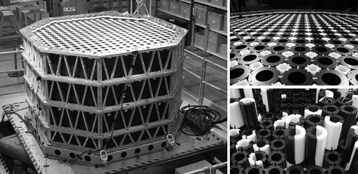
Ayatollahi, M.R., and Torabi, A.R., A criterion for brittle fracture in U-notched components under mixed mode loading, Engineering Fracture Mechanics 76, 1883-1896 (2009).
Birch, M., and Bacon, D.J., The effect of fast neutron irradiation on the compressive stress strain relationships of graphite, Carbon, Vol. 2(5), 491-496 (1983).
Blackburn, N.P., and Ford, P.J., Impact models for nuclear reactor graphite components under seismic loading, Nuclear Energy, 35, No. 6, 375-384 (1996).
Bodmann, E., Mechanical Design Philosophy for the Graphite Components of the Core Structure of an HTGR, IAEA Specialists Meeting on Graphite Component Structural Design, JAERI-M 86-192, Japan Atomic Energy Research Institute (JAERI), Tokai, Japan, 1987.
Bratton, R.L., 2009. Modeling mechanical behavior of a prismatic replaceable reflector block.
INL/EXT-09-15868, Idaho National Laboratory, Idaho Falls, ID.
A-75
Brocklehurst, J.E., and B.T. Kelly, Graphite Structure and Its Relationship to Mechanical Engineering Design, Specialists Meeting on Mechanical Behaviour of Graphite for HTRs, Gif-sur-Yvette, France, 11-13 June 1979, IWGHTR/3, International Atomic Energy Agency (IAEA)
International Working Group on High Temperature Reactors.
Burchell, T., HTGR Technology Course for the Nuclear Regulatory Commission, Module 9:
Graphite, Oak Ridge National Laboratory, May 24-27, 2010.
Busby, J., Garrison, L., Lin, L., Raiman, S., Sham, S., Silva, C., Wang, W., Iyengar, R., and Tartal, G., Technical Gap Assessment for Materials and Component Integrity Issues for Molten Salt Reactors, Oak Ridge National Laboratory Technical Report, ORNL/SPR-2019/1089, March (2019).
Davies, M., Graphite Presentation to USNRC in Support of PBMR Pre-application Activities Supporting Document, October 9, 2001, ADAMS Accession No. ML022320904.
Davis, M.A., and Bradford, M., A revised description of graphite irradiation induced creep, Journal of Nuclear Materials, Vol. 381, Issues 1-2, 31, pp. 39-45, October (2008).
Dihoru, L., O. Oddbjornsson, P. Kloukinas, M. Dietz, T. Horseman, T., E. Voyagaki, A.J. Crewe, C.A. Taylor, and A.G. Steer, The Development of a Physical Model of an Advanced Gas-Cooled Reactor Core: Outline of the Feasibility Study, Nuclear Engineering and Design, 323:269-279, 2017.
Carruthers, L.M., Butler, T.A., and Anderson, C.A., Thermal-stress analysis of a Fort St. Vrain core-support block under accident conditions, Los Alamos National Laboratory Report LA-UR-82-1920, presented at the Third Japan-U.S. HTGR Safety Technology Seminar Proceedings Held at Brookhaven National Laboratory, June 2-3 (1982).
Choi, S.R., and Salem, J.A., Indentation Flaw Formation and Strength Response of Silicon Nitride Ceramics at Low Indentation Loads, J. Mat. Sci. Lett., Vol. 11, No. 21, pp. 1398-1400 (1992).
Esnault, P., and M. Klein, Factors of Safety and Reliability: Present Guidelines and Future Aspects, Proceedings of the Conference on Spacecraft Structures, Materials and Mechanical Testing, Noordwijk, The Netherlands, March 27-29, 1996, ESA SP-386, European Space Agency.
Fang, X., Wang, H., and Yu, S., The Stress and Reliability Analysis of HTRs Graphite Component, Hindawi Publishing Corporation, Science and Technology of Nuclear Installations, Vol. 2014, Article ID 964848 (2014).
General Atomics (GA), MHTGR: New Production Reactor, Summary of Experience Base, GA-A-19152, March 1988.
General Atomics, Gas Turbine-Modular Helium Reactor (GT-MHR) Conceptual Design Description Report, GA-910720, Rev. 1, July (1996). (NRC ADAMS Accession No. ML022470282)
A-76
Gougar, H.D., The Application of the PEBBED Code Suite to the PBMR-400 Coupled Code Benchmark - FY2006 Annual Report," INL/EXT-06-11842, September 2006.
Ishihara, M., J. Sumita, T. Shibata, T. Iyoku, and T. Oku, Principle Design and Data of Graphite Components, Nuclear Engineering and Design, 233:251-260, 2004.
Jordan, M., Barhli, S. M., Copeland, G., Dinsdale-Potter, J., Tzelepi, A., Steer, A.G., Steer, D.,
Marrow, T.J., "Notch Sensitivity Measurements of Gilsocarbon Graphite Small Specimens,"
International Nuclear Graphite Specialists Meeting, September 2019.
Japan Atomic Energy Research Institute (JAERI), Graphite Structural Design Code for the High Temperature Engineering Test Reactor (HTTR), JAERI-M 89-006, 1989 [in Japanese].
Jones, C., Developments in the Prediction of Stresses and Deformations of Irradiated AGR Core Graphite Components, Transactions, SMiRT-23, 23rd Conference on Structural Mechanics in Reactor Technology, Division II, Transactions, SMiRT-23, Paper ID 149, Manchester, United Kingdom, August 10-14 (2015).
Judge, R.C.B., A Method for Assessing the Effects of Graphite Property Variability on Core Structural Integrity Criteria, The Status of Graphite Development for Gas Cooled Reactors:
Proceedings of a Specialists Meeting Held in Tokai-Mura, Japan, 9-12 September 1991, IAEA-TECDOC-690, pp. 78-84.
Judge, R.C.B., Application of a Method for Assessing Probability of Graphite Core Brick Failure, Graphite Moderator Lifecycle Behavior: Proceedings of a Specialists Meeting Held in Bath, United Kingdom, 24-27 September 1995, IAEA-TECDOC-901, 1996.
Ikushima, T., "A Computer Program for Seismic Analysis of the Two-Dimensional Vertical Slice HTGR Core," JAERI-1279, July 1982.
Kanse, D., I.A. Khan, V. Bhasin, and R.K. Singh, Interpretation of ASME Code Rules for Assessment of Graphite Components, Structural Mechanics in Reactor Technology 23 (SMiRT-23), Manchester, United Kingdom, August 10-14, 2015, Division II, Paper ID 346.
Kerntechnischer Ausschuss, Keramische Einbauten in HTR-Reaktordruckbehalten, KTA-3232, Sicherheitstechnische Regel des KTA, 1992. [The Nuclear Safety Standards Commission, "Ceramic Components in the Reactor Pressure Vessel," Safety Related Rule KTA-3232, 1992.
(Draft)]
Ho, F.H., Modified Weibull Theory and Stress-Concentration Factors of Polycrystalline Graphite, GA-A16197, General Atomic Company, December (1980).
Lejeail, Y., and Cabrillat, M.T., Calculation of thermal stresses in graphite fuel blocks, 18th International Conference on Structural Mechanics in Reactor Technology (SMiRT 18),
Paper: SMiRT18-W101-3, Beijing, China, August 7-12 (2005).
A-77
Li, H., Marsden, B.J., and Fok, S.L., Relationship between nuclear graphite moderator brick bore profile measurement and irradiation-induced dimensional change, Nuclear Engineering and Design 232, 237-247 (2004).
Li, H., Fok, A.S.L., and Marsden, B.J., An analytical study on the irradiation-induced stresses in nuclear graphite moderator bricks, Journal of Nuclear Materials 372, 164-170 (2008).
Marrow, T.J., Jordan, M.S.L., and Vertyagina, Y., Towards a notch-sensitivity strength test for irradiated nuclear graphite structural integrity, the 4th EDF Energy Nuclear Graphite Symposium, Engineering Challenges Associated with the Life of Graphite Reactor Cores,
©EMAS Publishing (2014).
Marsden, B.J., and G.N. Hall, Graphite in Gas-Cooled Reactors, Reference Module in Materials Science and Materials Engineering (S. Hashmi, ed.), Elsevier, Oxford, pp. 1-65, 2016.
Martinuzzi, P., T.-T.-G. Vo., V.X. Tran, A. Steer, S. Baylis, and N. McLachlan, Modelling Behaviour of AGR Graphite Core Using Code_Aster, presentation at the 16th International Nuclear Graphite Specialists Meeting, Nottingham, United Kingdom, September 13-17, 2015.
McLachlan, N., J. Reed, and M.P. Metcalfe, AGR Core Safety Assessment Methodologies, Graphite Moderator Lifecycle Behavior: Proceedings of a Specialists Meeting Held in Bath, United Kingdom, 24-27 September 1995, IAEA-TECDOC-901, 1996.
Metcalfe, M.P., ENCORE: A Model of Reactor Core Configuration and Loads, presentation at the 4th International Nuclear Graphite Specialists Meeting, Marugame, Japan, 2003.
Mitchell, B.C., Smart, J., Folk, A., Marsden, B.J., The Mechanical Testing of Nuclear Graphite, Journal of Nuclear Materials, Vol. 322, Nos. 2-3, pp. 126-137 (2003).
Mohanty, S. and Majumdar, S., HTGR Graphite Core Component Stress Analysis Research ProgramTask 1 Technical Letter Report, ANL-11/04, 2011, ADAMS Accession No. ML11276A009.
Mohanty, S., Jain, R., Majumdar, S., Tautges, T.J., and Srinivasan, M., Coupled Fluid-Structural Analysis of HTGR Fuel Brick Using ABAQUS, Proceedings of ICAPP 12, Paper 12352, Chicago, IL, June 24-28 (2012).
Mohanty, S., Majumdar, S., and Srinivasan, M., Constitutive modeling and finite element procedure development for stress analysis of prismatic high temperature gas cooled reactor graphite core components, Nuclear Engineering and Design 260, 145-154 (2013).
Moormann, R., A Safety Re-evaluation of the AVR Pebble Bed Reactor Operation and Its Consequences for Future HTR Concepts, Jül-4275 (ISSN 0944-2952), Forschungszentrum Jülich, Germany, 2008.
Jordan, M.S.L., Saucedo-Mora, L., Barhli, S., Nowell, D., and Marrow, J.T., Measurements of Stress Concentration Behavior in AGR Nuclear Graphite, 23rd Conference on Structural Mechanics in Reactor Technology, Manchester, United Kingdom, August 10-14 (2015).
A-78
Nemeth, N.N., and Bratton, R.L., Statistical Models of Fracture Relevant to Nuclear-Grade Graphite: Review and Recommendations, NASA/TM-2011-215805, National Aeronautics and Space Administration, Glenn Research Center, Cleveland, OH, March (2011).
Office for Nuclear Regulation, Graphite Reactor Cores, NS-TAST-GD-029, Revision 5, United Kingdom, November 2018.
Oku, T., and Ishihara, M., Lifetime evaluation of graphite components for HTGRs, Nuclear Engineering and Design 227, 209-217 (2004).
Orzáez, J.A., Neutronics Analysis of a Modified Pebble Bed Advanced High Temperature Reactor, Ph.D. thesis, The Ohio State University, 2009.
Prince, N., and J.E. Brocklehurst, The Integrity of CAGR Moderator Bricks, IAEA Specialists Meeting on Graphite Component Structural Design, JAERI-M 86-192, Japan Atomic Energy Research Institute (JAERI), Tokai, Japan, 1987.
Reed, J., Forward Strategy for Managing AGR Core Lifetime Engineering Challenges Associated with the Life of Graphite Reactor Cores, Papers from the 4th EDF Energy Nuclear Graphite Symposium, Nottingham, United Kingdom, May 6-9, 2014.
Riley, H., Physical Model of an AGR Nuclear Reactor Graphite Core for Shaking Table Explorations of Seismic Behaviour, South West Nuclear Hub, Bristol, UK, October 2018a.
Available from https://southwestnuclearhub.ac.uk/plex-agr-nuclear-graphite-core Riley, H., Analysis and Validation of Advanced Gas-Cooled Reactor Core Seismic Response Using Non-Linear Time-Domain Methods, presentation at the Meeting on Analysis and Validation of Advanced Gas-Cooled Reactor Core, Society for Earthquake and Civil Engineering Dynamics, London, United Kingdom, February 28, 2018b.
Roberts, J.G., Determination of Fatigue Characteristics of NBG18 Graphite, Ph.D. thesis, North-West University, Potchefstroom, South Africa, 2007.
Saito, S., T. Tanaka, and Y. Sudo, Design of High Temperature Engineering Test Reactor (HTTR), JAERI-1332, September 1994.
Schmidt, A., Design Methods and Criteria for Graphite Components, Proceedings of the Workshop on Structural Design Criteria for HTR, JÜL-CONF-71, Jülich, Germany, January 31-February 1, 1989, pp. 480-492.
Shi, D., Extension of the Reactor Dynamics Code MGT-3D for Pebblebed and Blocktype High-Temperature-Reactors, Ph.D. thesis, RWTH Aachen University, Forschungszentrum Jülich, 2015.
Shibata, T., M. Eto, E. Kunimoto, S. Shiozawa, K. Sawa, T. Oku, and T. Maruyama, Development of Japanese Technical Criteria for VHTR Graphite Components, presentation at the 10th International Nuclear Graphite Specialists Meeting, West Yellowstone, MT, September 28-30, 2009.
A-79
Shibata, T., M. Eto, E. Kunimoto, S. Shiozawa, K. Sawa, T. Oku, and T. Maruyama, Draft of Standard for Graphite Core Components in High Temperature Gas-Cooled Reactor, JAEA-Research-2009-042, Japan Atomic Energy Agency, 2010.
Shibata, T., HTGR Development in Japan and Present Status, presentation at Workshop V (VINCO Technical Meeting), 9th International School on Nuclear Power, Warsaw, Poland, 2017.
Singh, G., Li, H., Fok, A., and Mantell, S., Size Effect on the Fracture Properties of Nuclear Graphite, Graphite Testing for Nuclear Applications: The Significance of Test Specimen Volume and Geometry and the Statistical Significance of Test Specimen Population, STP 1578, Nassia Tzelepi and Mark Carroll, Eds., pp. 1-19, doi:10.1520/ STP157820130125, ASTM International, West Conshohocken, PA (2014).
Slavbonas, V., T.C. Stilwell, and Z. Zudans, Rules for Design of Nuclear Graphite Core ComponentsSome Considerations and Approaches, Nuclear Engineering and Design, 4:313-333, 1978.
Smith, P.D., Sullivan, R.M., Lewis, A.C., and Yu, H.-J., The Accuracy of Finite-Element Models for the Stress Analysis of Multiple-Holed Moderator Blocks, General Atomic Company, GA-A16234, February (1981).
Sterbentz, J. W., Calculated Neutron and Gamma-Ray Spectra Across the Prismatic Very High Temperature Reactor Core, 13th International Symposium on Reactor Dosimetry, Amsterdam, The Netherlands, May 2008.
Sullivan, R.M., and Griffen, J.E., Numerical Accuracy of Linear Triangular Finite Elements in Modeling Multi-Holed Structure, General Atomic Company, GA-A15605, June (1980).
Sumita, J., T. Shibata, T. Iyoku, K. Sawa, S. Hanawa, and M. Ishihara, Characteristics of First Loaded IG-110 Graphite in HTTR Core, JAEA-Technology-2006-048, 2006.
Taylor, R., Brown, R.G., Gilchrist, K., Hall, E., Hodds, A.T., Kelly, B.T., and Morris, F., The mechanical properties of reactor graphite, Carbon, Vol. 5, 519-531 (1967).
Tautges, T.J., and Jain, R., Creating geometry and mesh models for nuclear reactor core geometries using a lattice hierarchy-based approach, Journal of Engineering with Computers (2011).
Timoshenko, S., Strength of Materials, Part II: Advanced Theory and Problems, 2nd edition, Van Nostrand, New York, NY, 1941.
Tsang, D.K.L., and Marsden, B.J., The development of a stress analysis code for nuclear graphite components in gas-cooled reactors, Journal of Nuclear Materials, 350, 3 (2006).
Tucker, M.O., IAEA Technical Committee Mtg. on Mechanical Behaviour of Graphite for High Temperature Reactors, Gif sur Yvette, France, (1979).
A-80
Ueta, S., J. Aihara, N. Sakaba, M. Honda, N. Furihata, and K. Sawa, Fuel Performance under Continuous High Temperature Operation of the HTTR, Journal of Nuclear Science and Technology, 51:1345-1354, 2014.
U.S. Nuclear Regulatory Commission (NRC), Next Generation Nuclear Plant Phenomena Identification and Ranking Tables (PIRTs), Volume 5, Graphite PIRTs, NUREG/CR-6944, ORNL/TM-2007/147, March 2008, ADAMS Accession No. ML081140463.
U.S. Nuclear Regulatory Commission (NRC), Safety Aspects of HTR-Technology: NRC Visit in Germany, July 23-26, 2001a, ADAMS Accession No. ML092250104.
U.S. Nuclear Regulatory Commission (NRC), Safety Assessment of the HTR Module in Germany, July 26, 2001b, ADAMS Accession No. ML021960060.
Yu, S., Li, H., Wang, C., Zhang, Z., Probability assessment of graphite brick in the HTR-10, Nuclear Engineering and Design, (227) 133-142, 2004.
Yu, S., and L. Sun, The Design of HTR-PM Graphite Internals, Presentation at Nuclear Science and Engineering Institute, University of Missouri-Columbia, 2010.
Yu, S., H. Li, C. Wang, and Z. Zhang, Probability Finite Element Assessment Method for Nuclear Graphite Components, Transactions of the 17th International Conference on Structural Mechanics in Reactor Technology (SMiRT 17), Paper No. M04-5, Prague, Czech Republic, August 17-22, 2003.
Zhensheng, Z., Z. Zhengming, and S. Yu, Structural Design of Ceramic Internals of the HTR-10, presentation at the Meeting of the Nuclear Graphite Technology Research Group, September 29-October 5, 2002.
A-81
Appendix B On Establishing Temperature and Stress Limits
Appendix B On Establishing Temperature and Stress Limits
- 1. Introduction It is a perennial problem to decide how to establish limits in a consensus code and to characterize the technical bases that may support such limits. Often, sufficient experimental data or analytical models based on basic governing principles are not available. Even if data are available, they are always subject to the criticism that experimental conditions are not identical to reactor operational conditions. Also, questions arise about the reliability of data obtained from, for example, material test reactor (MTR) irradiation of test populations and subsequent postirradiation testing and analysis.
- 2. Discussion MTR test specimens usually deviate from the geometry and dimensions required for a robust property determination according to the standards of the American Society for Testing and Materials. The number of irradiated specimens may be too low to establish the effects of normal statistical variability as can be done for nonirradiated specimens. Reactor operators may at times wish to operate outside the temperature and fluence ranges of the graphite MTR database, which requires extrapolation. MTR irradiation may not accurately represent the simultaneous and synergistic effects of environmental degradation due to moisture or oxygen, which may be encountered in high-temperature gas-cooled reactor (HTGR) operation. There are also complications in extrapolating from data for small specimens to establish performance expectations for large components. Error! Reference source not found. shows how these uncertainties influence the establishment of suitable and conservative design stress and temperature limits.
B-1
Figure B-1 An example of a deliberative process to arrive at consensus design stress and temperature limits It is not possible to resolve all of these questions with a definitive technical basis. However, stress, fluence, and temperature limits can still be established conservatively. Here, two considerations play major roles. The first is the adequacy of actual operational data for the design; that is, previous reactor operation should have conformed to the temperature and stress limits imposed by the design code. The second is the availability of adequately vetted information from lessons learned. Any changes to the original stress limits should have gone through a consensus process.
In the absence of the two data sets described above, which are not always available for HTGRs, experts must deliberate and arrive at consensus temperature and stress limits to ensure reactor operating safety. With graphite components, it is generally recognized that graphite degradation, with proper monitoring and response, does not initiate or contribute to any radiological consequences. Thus, the designers primary consideration is usually the implications of plant shutdown. The economic consequences of shutdown include loss of revenue and the expense of inservice inspections and corrective actions required to return the reactor to service, including the expense of developing an acceptable safety case.
In the beginning, it is prudent to establish highly conservative temperature and stress limits, which can be relaxed as data from operating experience become available and are analyzed.
Such relaxation has been possible even for HTGRs where few, if any, operating experience data existed.
Yet another consideration, which is specific to graphite reactors, is the development of cracks after many years of reactor operation. Cracking may occur for various reasons. Delayed B-2
cracking may arise from a failure to accommodate internal stresses, while a crack may propagate because of environmental interactions with the crack front, which is a typical form of environmental degradation. Such cracking occurs even in graphite components that have experienced only stresses and temperatures within the code limits. Thus, arguably, cracks may be inevitable in a gas-cooled, graphite-moderated reactor. It is even possible that all graphite-based reactors may be operating with minor cracks that cannot be detected by existing examination methods.
B-3
Appendix C Graphite Damage Tolerance Operating Experience in Previous Gas-Cooled Reactors
ACRONYMS AND ABBREVIATIONS EDF Électricité de France FSV Fort St. Vrain Nuclear Generating Station PB-1 Peach Bottom Atomic Power Station, Unit 1 THTR Thorium High-Temperature Reactor ii
CONTENTS
- 1. Introduction ........................................................................................................................ C-1
- 2. Cracking in Graphite .......................................................................................................... C-1
- 3. Byproduct (Oxide) Deposition ............................................................................................ C-6
- 4. References ........................................................................................................................ C-8 LIST OF FIGURES Figure C-1 Cracking during operation of a Russian AV3 reactor (Platonov et al., 1995, Figure 4)
.................................................................................................................................................. C-2 Figure C-2 An example of a developed crack in a British Advanced Gas-Cooled Reactor (Reed, 2005, Slide 38) .......................................................................................................................... C-2 Figure C-3 Crack in fuel element 1-0172, which is widest at the top of the element and virtually disappears as it runs down the face of the element (Saurwein, 1982, Figure 3-19) ................. C-3 Figure C-4 Top surface view of the crack in fuel element 1-2415 (Saurwein, 1982, Figure 3-18(b)) ........................................................................................................................................ C-3 Figure C-5 Front view of longitudinal crack (Schwartz, 1969, Figure 6.31) ............................. C-4 Figure C-6 Fractured sleeve assembled on aluminum tube and oriented in the same position as suspected at PB-1 CCTV exam (Schwartz, 1969, Figure 6.32) ................................................ C-4 Figure C-7 PB-1 fuel sleeve suspected cracking as seen by CCTV (Schwartz, 1969, Figure 6.30) .......................................................................................................................................... C-4 Figure C-8 Cracks and residual fuel pebbles in the AVR bottom reflector (Wahlen et al., 2000, Figure 3).................................................................................................................................... C-5 iii
Appendix C Graphite Damage Tolerance Operating Experience in Previous Gas-Cooled Reactors
- 1. Introduction In past and currently operating gas-cooled reactors, graphite has shown remarkable tolerance to radiation damage involving dimensional changes, creep,1 microcracking, and both limited and extended cracking and crack advance. In each instance where damage could be detected by inspection, the reactor operator has examined the nature of the damage and developed a safety case for further damage tolerance in terms of maintaining adequate structural safety, thereby obtaining authorization to continue reactor operation. This appendix presents a few examples.
- 2. Cracking in Graphite The internal stresses generated by irradiation shrinkage (and expansion) lead to cracking and eventual swelling. Brohovich et al. (1958) disassembled an experimental uranium-graphite experimental reactor after four years of operation and studied the damage to the graphite core lattice. They found that internal stresses due to uneven dimensional changes in the brick had caused the initiation and propagation of longitudinal cracks.
Error! Reference source not found. shows an example of the accumulation of cracks in graphite, in a commercially operated reactor in Mayak, Russia. Here, the data indicate that several bricks have cracked within 24 years of operation.2 It is possible that some bricks had already experienced cracking that the reactor operator had been unable to detect. It is also apparent that relatively safe operation was possible even though more than half the bricks had cracks after some 27 years of operation. The coolant and control rods in this case were located and cooled by light water within aluminum or zirconium tubes passing through the graphite core.
The reactor tolerated extensive graphite component damage while maintaining core coolability and control rod insertion functions. However, there are other issues to consider, such as the removal of heat from the graphite stack; therefore, the safety of operating these reactors in such condition is questionable without more reliable information. In addition, such continued operation may not be allowed in the United States or elsewhere.
1 Unlike thermomechanical creep in metallic components, which is a function of applied stress and temperature and is related to increased plastic flow, graphite irradiation creep is a function of applied load (stress), irradiation temperature, and irradiation dose. Typically, the creep plot in metallic materials comprises creep strain versus applied stress at a constant temperature, together with creep strain versus temperature at a constant applied stress. The creep plot for graphite, on the other hand, comprises the creep deformation response to dose at a constant temperature for varying loads, together with creep strain versus dose at a constant load (stress) for varying irradiation temperatures.
Graphite creep during reactor operation is actually beneficial, because it reduces dimensional change and thus reduces deformation-induced and other loading-related stresses.
2 Dr. Barry Marsden, an author of this report, has visited this reactor site in the past. He observed that the cracking was so severe that as the brick cracks had opened, the restraint band around the reactor had broken. The restraint was modified, and the reactor continued to operate for a number of years afterwards.
C-1
Figure C-1 Cracking during operation of a Russian AV3 reactor (Platonov et al., 1995, Figure 4)
Cracks have been encountered in other graphite reactors as well. Error! Reference source not found. shows an example from an Advanced Gas-Cooled Reactor in the United Kingdom.1 Figure C-2 An example of a developed crack in a British Advanced Gas-Cooled Reactor (Reed, 2005, Slide 38) 1 The operator of the reactor has posted video footage, which is available from https://www.bing.com/videos/search?q=hunterston+b+edf+video&view=detail&mid=C2A57DCFD0E053E16 F22C2A57DCFD0E053E16F22&FORM=VIRE (accessed May 20, 2019).
C-2
After what was then British Energy (now Électricité de France (EDF)) provided a revised safety case for continued operation, the United Kingdoms regulator assessed the safety case and approved the continuation of reactor operation. In this reactor, the main coolant path for the fuel is located inside a series of graphite sleeves, which separate the moderator bricks from the fuel.
These graphite sleeves are replaced on refueling. This mitigates the potential adverse effects of moderator brick cracking. In addition, the control rod channels are at a distance from the fuel where the flux and temperature are more uniform, and no cracking has been observed.
Cracks also occurred during the operation of the Fort St. Vrain Nuclear Generating Station (FSV). After refueling operations examination results showed the bricks to be generally in the original as-installed condition, with no chips, breaks, gouges, or broken dowel pins (Saurwein, 1982). However, at the first refueling, it was found that two adjacent blocks had developed vertical hairline cracks extending from the outside face to the nearest cooling hole (Error! Reference source not found. and Error! Reference source not found.). Such cracking was determined to be the result of unintended coolant flow between the gaps essentially a bypass flow that had not previously been expected. Reactor operation continued, and after two more refueling operations, no further cracks were observed. Thus, the initial occurrence of the two hairline cracks was deemed not to be a safety issue (General Atomics, 1988).
Figure C-3 Crack in fuel element 1-0172, Figure C-4 Top surface view of the which is widest at the top of the element and crack in fuel element 1-2415 (Saurwein, virtually disappears as it runs down the face 1982, Figure 3-18(b))
of the element (Saurwein, 1982, Figure 3-19)
C-3
Cracks were also seen in 90 fuel element sleeves in the Peach Bottom Atomic Power Station, Unit 1 (PB-1), reactor. These cracks were due to radial expansion and distortion of fuel compacts, which had caused them to bind against the graphite sleeves (Kingery, 2003). Error!
Reference source not found., Error! Reference source not found., and Error! Reference source not found. show an example of such cracking (Schwartz, 1969). Since the Peach Bottom inspection pictures did not show the apparent massive fracture observed initially in the hot cell at Gulf General Atomic, it is clear that the massive fracturing of the sleeve did not occur during irradiation. Rather, the fracture was due to the handling of the halves of the fuel element at Peach Bottom. While sleeve cracks are considered fuel element failures, the occurrence of these cracks and the consequent gradual increase in coolant activity did not significantly affect plant operations. According to the operator, the plant could be operated with many tens of such failures in the core without exceeding applicable safety limits or technical specifications (Schwartz, 1969).
Figure C-5 Front view of Figure C-6 Fractured sleeve Figure C-7 PB-1 fuel longitudinal crack assembled on aluminum tube sleeve suspected (Schwartz, 1969, and oriented in the same cracking as seen by Figure 6.31) position as suspected at PB-1 CCTV (Schwartz, 1969, CCTV exam (Schwartz, 1969, Figure 6.30)
Figure 6.32)
Error! Reference source not found. illustrates another instance of graphite component cracking in an experimental reactor. Wahlen et al. (2000) observed that cracking of bottom reflector components and their slight movement in the AVR led to the widening of coolant penetration slits. This, in turn, caused the fuel pebbles to become stuck in these slits and not roll off into the fuel discharge pipe during refueling. The operators were able to remove some using the manipulator, but many remained stuck.
C-4
Figure C-8 Cracks and residual fuel pebbles in the AVR bottom reflector (Wahlen et al.,
2000, Figure 3)
According to Wahlen et al. (2000), after the defueling of the Thorium High-Temperature Reactor (THTR), it was observed that cooling channels were blocked by scrap from broken fuel elements. The Hochtemperatur-Kernkraftwerk GmbH utility, which operated the THTR, assumed that the breaking of the fuel pebbles had mainly been caused by multiple insertions of the in-core absorber rods without lubrication from the injection of ammonia gas. (The presence of the ammonia gas reduced the friction coefficient when absorber rods were driven into the pebble bed core.) The licensing authorities requested repeated tests to demonstrate the function of the absorber rods in cases where the injection of ammonia would not work. The pictures taken support the assumption that most of the scrap consisted of the fuel-free 5-millimeter-thick (0.2-inch-thick) outer layer of the spherical fuel element. One picture shows that each borehole is conically widened (like an egg cup) at the surface towards the pebble bed.
In addition, the holes are arranged in a hexagonal pattern and have a pitch of 6 centimeters (2.4 inches), which equals the diameter of the fuel pebbles. Therefore, it cannot be ruled out that the pebbles became immobilized in a regular configuration when flowing over the bottom reflector. This effect could also have contributed to fuel pebble damage and to the unexpected pebble flow. Thus, it seems that such geometries need to be avoided for any pebble-design high-temperature gas reactor.
Interestingly, the U.S. Nuclear Regulatory Commission staff raised a related issue in Request for Additional Information 1.2.36, in response to a presentation on graphite in pebble bed modular reactors (NRC, 2002). The staff concern pertained to small absorber spheres falling freely (under gravity) into the holes in the side reflectors, which have no shock absorber. The staff wanted to know how this impact would affect the spheres and the side or bottom reflector blocks.
In summary, many commercial graphite-moderated reactors have been permitted to continue operation despite the presence and propagation of cracks in components. This is because they could still operate safely: the cracked graphite components continued to adequately perform C-5
their intended functions. Their cracks did not compromise their overall ability to moderate and reflect neutrons and act as shields. In each case, the licensee was able to demonstrate that component fractures were tolerable, because the reactor maintained the required geometry in (1) the control rod channels (for insertion and withdrawal of control rods for reactivity control),
(2) the fuel channels (for defueling and refueling), and (3) the coolant channels (for sufficient coolant flow).
- 3. Byproduct (Oxide) Deposition Wear and erosion during reactor operation may damage graphite components in a gas-cooled reactor. In the case of a pebble bed reactor, the motion of spherical fuel pebbles creates impact and friction, wearing out the graphite1 pebble surfaces and generating carbon dust particles, which may be deposited on the graphite moderator as stain in localized areas. The coolant also carries such dust. Additionally, fuel spheres directly striking the graphite moderator or rolling along its sides can cause erosion. This generates graphite dust, which may again be loosely deposited on the moderator or carried along by the coolant.
Localized oxidation may also be expected in gas-cooled reactors. Error! Reference source not found. shows an example of possible oxidation in the FSV reactor. Several fuel elements in the FSV reactor also exhibited scratches, as shown in Error! Reference source not found..
Finally, if any oil leakage occurs, oil may decompose and be deposited as carbon in the form of soot on both fuel spheres and the graphite moderator. Error! Reference source not found.
shows an example of such a deposit.
1 The outer layer of a fuel pebble is not truly graphite, as it has undergone heat treatment at a temperature substantially below graphitization temperature (i.e., the temperature required to form the crystalline lattice structure of graphite). Because it has been heat treated at about 1,800 degrees C (3272 degrees F), it is really carbon. Two major mechanisms, among others, operate in the friction between fuel spheres. First, friction between like pairs may cause sticking, depending on the fluid dynamics of the coolant flow. Second, sliding wear may occur, which actually generates carbon dust and not graphite dust in this case.
C-6
Figure C-9 Possible oxide deposit on a reflector face in the FSV reactor (Saurwein, 1982, Figure 3-6)
Figure C-10 Scratches on an FSV fuel element Figure C-11 Soot deposit on a (Saurwein, 1982, Figure 3-9) graphite control rod element in the FSV reactor (Saurwein, 1982, Figure 3-12)
C-7
- 4. References Brohovich, B.B., F.I. Ovichinnikov, V.I. Klimenkov, P.V. Glazkvo, and B.M. Dolishnyuk, Disassembly of an Experimental Uranium-Graphite Isotope Reactor after Four Years of Operation, Proceedings of 2nd U.N. International Conference on Peaceful Uses of Atomic Energy, Geneva, September 1-13, 1958, Session E-21, Vol. 7, Paper 2297, pp. 241-249.
General Atomics (GA), MHTGR: New Production Reactor, Summary of Experience Base, GA-A-19152, March 1988.
Kingery, K.I., Fuel Summary for Peach Bottom Unit 1 High-Temperature Gas-Cooled Reactor Cores 1 and 2, INEEL/EXT-03-00103, Idaho National Laboratory, 2003.
Platonov, P.A., O.K. Chugunov, V.N. Manesvsky, and V.I. Karpikum, Radiation Damage and Life-time Evaluation of RBMK Graphite Stack, Graphite Moderator Lifecycle Behavior:
Proceedings of a Specialists Meeting Held in Bath, United Kingdom, 24-27 September 1995, IAEA-TECDOC-901, 1996, pp. 79-89.
Reed, J., An Update on Results from Inspection of AGRs, presentation at the 6th International Nuclear Graphite Specialists Meeting, Chamonix, France, 2005.
Saurwein, J.J., Nondestructive Examination of 54 Fuel and Reflector Elements from Fort St.
Vrain Core Segment 2, GA-A16829, General Atomics, 1982.
Schwartz, A., Postirradiation Examination of Peach Bottom Fuel Elements E05-05 and CO5-05 and Related Analyses, GAMD-8743, Gulf General Atomic, 1969.
U.S. Nuclear Regulatory Commission (NRC), Request for Additional Information (RAI) on High Temperature Materials Graphite; Control of Chemical Attack; and Design Codes and Standards for the Pebble Bed Modular Reactor (PBMR), letter from Farouk Eltawila to Kevin Borton, Exelon Generation, May 31, 2002, Agencywide Documents Access and Management System Accession No. ML021510521.
Wahlen, E., J. Wahl, and P. Pohl, Status of the AVR Decommissioning Project with Special Regard to the Inspection of the Core Cavity for Residual Fuel, Waste Management 00 Conference, Tucson, AZ, February 27-March 2, 2000.
C-8
Appendix D Reconciliation of NRC Graphite Phenomena Identification and Ranking Tables with Industry Design Data Needs as Related to the Requirements of the American Society of Mechanical Engineers Boiler and Pressure Vessel Code,Section III, Division 5, High Temperature Reactors, Subsection HH, Class A Nonmetallic Core Support Structures, Subpart A, Graphite Materials
ACRONYMS AND ABBREVIATIONS AGR Advanced Gas-Cooled Reactor ASME American Society of Mechanical Engineers ASTM American Society for Testing and Materials AVR Arbeitsgemeinschaft Versuchsreaktor BPVC Boiler and Pressure Vessel Code C Celsius CSC core support components CTE coefficient of thermal expansion DDN design data need DOE U.S. Department of Energy dpa displacements per atom DPP demonstration power plant F Fahrenheit FOM figure of merit FP fission product GA General Atomics GCC graphite core component GIF Generation IV International Forum HTGR high-temperature gas-cooled reactor HTR high-temperature reactor IAEA International Atomic Energy Agency ISI inservice inspection MHTGR modular high-temperature gas-cooled reactor MTR material test reactor MW megawatt MWe megawatt electric ii
MWth megawatt thermal NEA Nuclear Energy Agency NGNP Next Generation Nuclear Plant NRC U.S. Nuclear Regulatory Commission PBMR pebble bed modular reactor PIRT phenomena identification and ranking table RG regulatory guide Sg design equivalent stress THTR Thorium High-Temperature Reactor WEC Westinghouse Electric Company iii
CONTENTS Purpose ............................................................................................................................. D-1 NRC Graphite Research Workshop (2009) ....................................................................... D-3 Industry Design Data Needs .............................................................................................. D-5 Relationships among the NRC Phenomena Identification and Ranking Tables, Industry Design Data Needs, and ASME BPVC, Subsection HH, Subpart A................................ D-10 Nonirradiated Properties ............................................................................................. D-11 4.1.1 Strength and Strength Distribution .................................................................... D-11 4.1.2 Flaws in Graphite .............................................................................................. D-12 4.1.3 Tribology ............................................................................................................ D-13 4.1.4 Cyclic Fatigue .................................................................................................... D-14 Irradiation-Induced Changes in Properties .................................................................. D-16 4.2.1 Emissivity .......................................................................................................... D-16 4.2.2 Dimensional Change ......................................................................................... D-17 4.2.3 Changes in the Coefficient of Thermal Expansion, Including the Effects of Creep Strain ..................................................................... Error! Bookmark not defined.
4.2.4 Changes in Mechanical Properties .................................................................... D-19 4.2.5 Graphite Pore Structure .................................................................................... D-21 4.2.6 Oxidation of Irradiated Graphite ........................................................................ D-22 4.2.7 Degradation of Thermal Conductivity ................................................................ D-23 4.2.8 Annealing of Thermal Conductivity .................................................................... D-24 4.2.9 Blockage of Fuel Element Coolant Channel (Prismatic Fuel)............................ D-25 4.2.10 Foreign Objects (Debris) ................................................................................. D-26 4.2.11 Blockage of Coolant Channel in Reactivity Control Block Due to Graphite Failure, Graphite Spalling, or Both ............................................................................... D-27 4.2.12 Fuel Flow Blockage (Pebble Bed) ................................................................... D-28 4.2.13 Blockage of Reflector Block Coolant Channel Due to Graphite Failure and Spalling ............................................................................................................ D-29 4.2.14 Effects of Channel Distortion (Radiation Damage) .......................................... D-30 4.2.15 Bypass Flow Increase ..................................................................................... D-31 4.2.16 Outlet Plenum Collapse ................................................................................... D-32 4.2.17 Chemical Attack .............................................................................................. D-33 4.2.18 Catastrophic Chemical Attack ......................................................................... D-34 iv
4.2.19 Effect of Chronic Chemical Attack on Properties............................................. D-35 4.2.20 Effect of Chronic Chemical Attack on Properties............................................. D-36 4.2.21 External (Applied Loads) ................................................................................. D-37 4.2.22 Fast Neutron Fluence ...................................................................................... D-38 4.2.23 Gamma and Neutron Heating ......................................................................... D-39 4.2.24 Graphite Temperatures ................................................................................... D-40 4.2.25 Consideration of Multiaxial Stress State in Graphite Components .................. D-41 4.2.26 Graphite Quality .............................................................................................. D-42 References ...................................................................................................................... D-43 LIST OF FIGURES Figure D-1. NRC graphite PIRT influencing factors to consider in component design ............ D-3 Figure D-2. System configuration for AREVA NGNP concept (AREVA, 2009, Figure 3-1) ..... D-6 Figure D-3. NGNP reactor module proposed by GA (GA, 2019, Figure 2) .............................. D-7 Figure D-4. Horizontal cross section of the PBMR core (Mitchell, 2004, p. 10) ....................... D-8 Figure D-5. Vertical cross section of the PBMR core (Mitchell, 2004, p. 9) ............................. D-8 Figure D-6. HTGR process heat price versus module and plant rating (Shahrokhi, 2019, p. 6) ....
.................................................................................................................................................. D-9 LIST OF TABLES Table D-1 FOMs for Graphite Phenomena .............................................................................. D-2 Table D-2 Topics from the NRC PIRT Pertaining to ASME BPVC, Subsection HH, Subpart A; Related Industry DDNs; and Recommendations for NRC Review ...................... D-11 v
Appendix D Reconciliation of NRC Graphite Phenomena Identification and Ranking Tables with Industry Design Data Needs as Related to the Requirements of the American Society of Mechanical Engineers Boiler and Pressure Vessel Code,Section III, Division 5, High Temperature Reactors, Subsection HH, Class A Nonmetallic Core Support Structures, Subpart A, Graphite Materials
- 1. Purpose This appendix examines the items from the U.S. Nuclear Regulatory Commission (NRC) phenomena identification and ranking table (PIRT) and related industry design data needs (DDNs)1 that pertain to the 2017 American Society of Mechanical Engineers (ASME) Boiler and Pressure Vessel Code (BPVC),Section III, Subsection HH, Class A Nonmetallic Core Support Structures, Subpart A, Graphite Materials. The appendix documents information used in the assessment of Subsection HH, Subpart A, and provides information to support the development of future NRC regulatory guidance.
In the past, designers of gas-cooled reactors have developed DDNs to support their assumptions in meeting structural integrity requirements. This appendix discusses Subsection HH, Subpart A, in relation to such DDNs. It establishes a link between the results of the NRC PIRT exercise conducted in 2007 (documented in NUREG/CR-6944, Next Generation Nuclear Plant Phenomena Identification and Ranking Tables (PIRTs), Volume 5, Graphite PIRTs, issued March 2008 (NRC, 2008)), designers DDNs for various graphite properties, and the authors assessment of how Subsection HH, Subpart A, includes or excludes these phenomena and concerns.
Table D-2 contains recommendations on additional needs that the NRC staff might consider in developing regulatory guidance documents. These recommendations are tied to PIRT findings, industry DDNs, and the related requirements of Subsection HH, Subpart A, for particular aspects of design. Their fulfillment should clarify how data and methods can be used to provide assurance of structural integrity.
NRC Phenomena Identification and Ranking Tables (2008)
The NRC used the PIRT process to assess safety-relevant Next Generation Nuclear Plant (NGNP) phenomena, based on the opinions of subject-matter experts, and to rank these phenomena in terms of their importance and the state of knowledge about them so that research could be pursued to address important knowledge gaps. The graphite PIRT process had the following eight steps:
(1) Identify issues.
1 DDNs identify research and development activities that designers need to validate the assumptions they have made during the iterative, top-down design process. DDNs also highlight gaps in the understanding of the technical bases used for design, which may lead to additional burden in the regulatory licensing process.
D-1
(2) Define PIRT objectives.
(3) Identify hardware and scenario.
(4) Evaluate criteria.
(5) Identify knowledge base.
(6) Identify phenomena.
(7) Rank importance.
(8) Identify knowledge-level ranking.
The PIRT review evaluated graphite-related phenomena against figures of merit (FOMs) based on regulatory, system, and component perspectives (Table 1-1). The primary FOM was that of maintaining the dose at the site boundary within regulatory limits. The PIRT review identified the graphite degradation phenomena for structures, systems, and components in high-temperature gas-cooled reactors (HTGRs) that could reduce the available safety margin during normal reactor operation, off-normal anticipated occurrences, design-basis accidents, and beyond-design-basis accidents. The PIRT process assessed the relative importance of several phenomena based on a consensus FOM and evaluated whether current understanding of each phenomenon could provide adequate technical information for regulatory safety decisions.
Table 1-1 FOMs for Graphite Phenomena Level 1 Regulatory Related to dose consequence
- 1. Increased activity in the coolant
- 2. Challenges to primary pressure boundary Level 2 System
- 3. Degraded ability for cold shutdown and holddown
- 1. Maintaining the ability for passive heat transfer
- 2. Maintaining reactivity control
- 3. Thermal protection of adjacent components
- 4. Shielding of adjacent components Level 3 Component
- 5. Maintaining coolant flow path
- 6. Preventing excessive mechanical load on the fuel
- 7. Minimizing activity in the coolant The present analysis concentrates on several phenomena. These are phenomena whose handling in Subsection HH, Subpart A, deemed to require scrutiny. For these phenomena, if there are insufficient data, few analytical models, and a lack of understanding, these limitations will hamper the design of graphite components and may compromise the functions described in the third column of Table 1-1. To improve regulatory guidance on these phenomena, a link needs to be established between the pertinent articles in Subsection HH, Subpart A, and the NRC PIRT results. In addition, it is prudent to examine how HTGR designers plan to address the knowledge gaps in order to develop robust safety analyses.
D-2
Figure D-1 summarizes the evaluation criteria for graphite components and the general properties and phenomena that affect PIRT results and thus need to be considered in component design.
Figure D-1 NRC graphite PIRT influencing factors to consider in component design
- 2. NRC Graphite Research Workshop (2009)
In March 2009, the NRC conducted a workshop on graphite research needed in the technical areas that the 2007 graphite PIRT review had scored as having high or medium importance to reactor safety, but for which technical knowledge was low (Gallego et al., 2009; NRC, 2009).
Workshop participants discussed five high-importance, low-knowledge phenomena:
(1) irradiation-induced creep (irradiation-induced dimensional change under stress)
(2) irradiation-induced change in the coefficient of thermal expansion (CTE), including the effects of creep strain (3) irradiation-induced changes in mechanical properties (strength, toughness), including the effects of creep strain (stress)
(4) blockage of a fuel element coolant channel due to graphite failure, graphite spalling, or both (5) blockage of a coolant channel in the reactivity control block due to graphite failure, graphite spalling, or both D-3
Workshop discussions made it clear that there is a need for more specific and detailed data, together with sound data analysis and evaluation, especially for newer graphites. Designers can use such data to model graphite component behavior, providing assurance of required structural integrity and potentially satisfying regulatory review and assessment requirements.
Many challenges in the safety evaluation of HTGR graphite components arise in relation to the models and data used to estimate the probability of (functional) failure of graphite components, which contributes to the HTGRs overall core performance risk measures. Such models include the following:
- the graphite material degradation model, based on limited material test reactor (MTR) data1 and operating experience
- a scaled-up of the model in the first item, used to extrapolate and translate its results from test specimens to actual reactor components
- the graphite component structural integrity model, based on a finite element stress analysis and fracture analysis (behavior) model
- models for online and in situ monitoring and inspection of graphite components These models and their interactions have limitations due to the following six factors:
(1) data and model uncertainties (2) lack of verification and validation of data and models (3) lack of adequate operating experience (4) incomplete mechanistic understanding (5) variations in reactor operation (6) inconsistencies in the definition of graphite component failure, affecting estimates of the range of failure probabilities When the initial risk measure is very low, designers may tend to ignore potential model weaknesses (incompleteness). Typically, the robustness of any model in predicting component behavior depends on the quality, quantity, and reliability of the input information.
The safety case for operability with degraded graphite components depends on the adequacy of inspections and on the confirmation of model predictions of graphite behavior by inspection 1 For some important properties, plenty of MTR data are generally available; for example, for the United Kingdoms Advanced Gas-Cooled Reactors (AGRs), abundant MTR data are available on dimensional change, modulus, CTE, and thermal conductivity. For other properties, such as creep, failure, fracture crack growth, and the effect of strain on CTE, only sparse data are available. This is because MTR experiments in the latter areas are difficult to perform and often fail in their implementation. In addition, the scientific analysis required to reach mechanistic understanding has been limited in extent, poorly implemented, and lacking in rigor.
D-4
data. Thus, broadly, Subsection HH, Subpart A, should provide rules and suggested procedures for the following seven items:
(1) component failure criteria, graded on safety significance (2) component performance criteria (3) component inspection criteria, including inspection for debris collection in parts of the coolant circuit (4) requirements for core surveillance activities such as monitoring of the core temperature, core restraint system, and core support structure; testing protocols; and procedures to assess their efficacy (5) requirements for core surveillance using coupons and core sampling (trepanning)
(6) acceptance/replacement criteria for flawed graphite components in service (7) requirements for the graphite component degradation management program, and procedures to assess program efficacy Arguably, Subsection HH, Subpart A, has not yet addressed item (6) in the above list, but the user must develop these and provide them to the NRC staff for evaluation and acceptance.
- 3. Industry Design Data Needs HTR designers have often been limited by the unavailability of data on thermal and mechanical properties for the graphite core components (GCCs) in their designs. Graphite manufacturers have often provided prototypical component-size billets for property characterization; however, these mostly yield data on as-manufactured and nonirradiated properties (also known as properties on virgin graphite). Over the last two decades, various international research programs have attempted to use MTRs to study irradiated properties for newer grades of graphite. However, because of the high cost of such research, the difficulty of some MTR procedures (such as the use of creep test rigs), and the time needed to obtain data on irradiated properties, the transition from prototype to actual large-volume production of billets has not taken place to any appreciable degree for many nuclear-grade graphites. Although data on elastic properties and strength may be available for various irradiation temperatures and neutron doses, data on irradiation creep, influence of creep strain on CTE, and modulus and fatigue are not generally available. Data on thermal properties, such as thermal diffusivity, conductivity, and emissivity, are also sparse. Nor are there usable data on the corrosion of irradiated graphite in typical reactor environments, such as environments containing high-temperature circulating helium and scenarios involving moisture and air ingress.
This lack of data makes it difficult not only to establish the structural integrity and reliability of GCCs in HTGRs, but also to conduct reliable thermal fluid analysis and heat conduction analysis for accident scenarios, including those involving the intrusion of air, moisture (limited water), or water. Therefore, designers have always established DDNs to identify research that D-5
could improve operational reliability while reducing the unnecessary margins (or factors of safety, for structural integrity) that are necessary in the absence of reliable data.
The AREVA DDN covered here is based on AREVAs conceptual design of a prismatic HTGR (600 megawatts thermal (MWTh)) with a reactor core inlet temperature of 350 degrees Celsius (C) (662 degrees Fahrenheit (F)), a reactor core outlet temperature of 750 degrees C (1382 degrees F), and a first-of-its-kind conventional steam cycle concept. Figure D- (AREVA, 2009) shows the configuration.
Figure D-2 System configuration for AREVA NGNP concept (AREVA, 2009, Figure 3-1)
GA Technologies, Inc., published its document on DDNs in 1987 (GA Technologies, Inc.,
1987a). Its design was for a conceptual prismatic reactor comprising four reactor modules and two turbine generator sets, for a nominal plant rating of 558 megawatts electric (MWe) (GA Technologies, 1987b). The cold helium coolant temperature at circulator discharge was 258 degrees C (496 degrees F), and the hot helium temperature at the exit of the core was 687 degrees C (1269 degrees F). Although GA Technologies made substantial efforts in the preconceptual and conceptual design phases, including interactions with the NRC to explore licensing approaches, it eventually abandoned the project. However, the DDNs generated at that time for H-451 graphite are still pertinent for newer graphites. Therefore, this report includes information from these DDNs.
In 2009, in response to the U.S. Department of Energys (DOEs) NGNP solicitation, General Atomics (GA) proposed the Gas Turbine Modular Helium Reactor (GIF, 2002; GA, 2019).
Figure D- shows the proposed module configuration. The conceptual design had an output of 600 MWt, with a core helium inlet temperature of 491 degrees C (916 degrees F) and an outlet temperature of 850 degrees C (1562 degrees F). The power conversion system was designed to use the Brayton cycle. GA provided DDNs to the DOE in the form of technology readiness level rankings (GA, 2009). This report includes some of the relevant DDNs.
D-6
Figure D-3 NGNP reactor module proposed by GA (GA, 2019, Figure 2)
D-7
During the NGNP preconceptual design phase, in 1989, the Westinghouse Electric Company (WEC)/Pebble Bed Modular Reactor (PBMR) Team devised DDNs for technology development building on that conducted for the PBMR demonstration power plant (DPP) to be built at Koeberg, South Africa. The DPP was designed as a direct-cycle 400-megawatt (MW)
(175-MWe) PBMR with a core outlet temperature of 900 degrees C (1652 degrees F). The PBMR core is based on the HTGR technology originally developed in Germany (NRC, 2006).
The pebble fuel has the size and physical characteristics of the pebble fuel developed for the German high-temperature reactor (HTR) program. However, instead of using the German power conversion configuration, which was a gas-to-steam cycle heat exchanger, the PBMR uses a direct (Brayton) cycle power conversion configuration, with helium as the working fluid.
The core coolant inlet temperature is 250 degrees C (482 degrees F), and the core coolant outlet temperature is 750 degrees C (1382 degrees F) (IAEA, 2011). Figure D- and Figure D- respectively show the horizontal cross section (Mitchell, 2004 and Venter, Mitchell, and Fortier, 2005) and the vertical cross section of the PBMR core, with a center reflector as a new design feature (NEA, 2013; Mitchell, 2004).
SAS Channels Reactor Pressure Fuel Line Vessel Core Barrel Top Reflector Fuel Core Side Fuel Core Reflector Centre Control Rod Gas Riser Reflector Channels Centre Reflector Side Reflector SAS Control Rod Channels Channel Bottom Reflector SAS Extraction Point Figure D-4 Horizontal cross section of the PBMR Figure D-5 Vertical cross section of the core (Mitchell, 2004, p. 10) PBMR core (Mitchell, 2004, p. 9)
The WEC/PBMR Team proposed a pebble bed design, adapting the South African PBMR design for the NGNP very-high-temperature reactor. This concept design was for a 400-MWth reactor with a core inlet temperature of 500 degrees C (932 degrees F) and a core outlet temperature of 900 degrees C (1652 degrees F) (Tong et al., 2015). The general arrangement D-8
and principles underlying the design of the core structure graphite components are based on the German designs for the Thorium High-Temperature Reactor (THTR) and later reactors (WEC, 2009a). The WEC/PBMR Team developed a DDN document for this concept reactor (WEC, 2009b).
In 2010, the WEC/PBMR Team withdrew its design certification application and canceled all further engagement with the NRC. Subsequently, the South African PBMR project was also abandoned. In 2012, the NGNP Industry Alliance selected the AREVA design for further support for commercialization (NGNP Industry Alliance, 2012). The choice was apparently based on economic projections that capital costs for a plant with an installed capacity of 2,400-3,000 MWt would be some 30 percent less using 625-MWt prismatic reactor modules than using 250-MWt pebble bed modules (Figure D-) (World Nuclear News, 2012; AREVA, 2004).
Figure D-6 HTGR process heat price versus module and plant rating (Shahrokhi, 2019,
- p. 6)
Since the AREVA design, supported by the NGNP Industry Alliance, may soon be ready for submission to the NRC for design certification, the AREVA DDNs are most appropriate for analysis here. However, for the sake of completeness, this report also analyzes the WEC/PBMR and GA DDNs, as well as the earlier DDNs for the GA Technologies modular high-temperature gas-cooled reactor (MHTGR) (GA Technologies, Inc., 1987a). This allows D-9
more thorough cross-checking of the general technical requirements and of their handling in Subsection HH, Subpart A.
- 4. Relationships among the NRC Phenomena Identification and Ranking Tables, Industry Design Data Needs, and ASME BPVC, Subsection HH, Subpart A Table 4-1 links the 2007 NRC graphite PIRT phenomena of concern with the relevant articles and subarticles of Subsection HH, Subpart A, and with the relevant industry DDNs. It also includes industry comments and plans for addressing the phenomena of concern, and it lists areas recommended for further review by the NRC staff when developing regulatory guidance.
D-10
Table 4-1 Topics from the NRC PIRT Pertaining to ASME BPVC, Subsection HH, Subpart A; Related Industry DDNs; and Recommendations for NRC Review Nonirradiated Properties 4.1.1 Strength and Strength Distribution NRC PIRT (2008) PIRT rank1 Subsection HH, PIRT ID Industry DDN Industry disposition Recommendation phenomenon/concern Subpart A GA Technologies (1987a) GA Technologies planned (in 1987) to use Stackpole 2020 The Code considers this concern adequately.
1 Due to the inherent I = H, K = M HHA-3237 Design Stress MHTGR graphite for the core support structure, to meet the nonhomogeneity of Values and Material M.10.17.01 requirements in the proposed ASME BPVC,Section III, microstructural constituents in Properties M.10.17.02 Division 2, Subsection CE, Design Requirements for Graphite graphite, considerable scatter M.10.18.03 Core Supports (ASME, 1990),2 and to obtain uniaxial strength could exist in the strength data, data.
thus making the use of Probabilistically based stress criteria are used to ensure deterministic methods compliance with the reliability requirements. The statistical unsuitable. The statistical variability of the mechanical properties of GCCs becomes an variation of nonirradiated input to the development of these criteria.
properties needs to be GA (2009) GA decided to conduct tests and establish a database. This considered in the design. C.11.03.13 (Graphite includes irradiation testing.
Mechanical Properties Data)
WEC-PBMR (WEC, 2009b) See Note 1 at the end of this table.
PBMR NGNP AREVA (2009) Statistical variation of nonirradiated properties needs to be 2.4.1.0 incorporated (variability in properties (textural and statistical));
isotropic. Use of a probabilistic approach is prudent.
Required characterization is complete for NBG-18 for the DPP.
See Note 2 at the end of this table.
1 I = importance, K = knowledge; H = high, M = medium, L = low.
2 Hereafter referred to as the ASME draft CE Code.
D-11
4.1.2 Flaws in Graphite PIRT NRC PIRT (2008) PIRT rank Subsection HH, Industry DDN Industry disposition Recommendation ID phenomenon/concern Subpart A It is known that graphite HHA-4233.2 GA Technologies (1987a) Nondestructive testing techniques The review, as discussed in 3 I = M, K = M contains inherent flaws. Material M.10.18.10 (Core Graphite are needed for product control TLR/RES/DE/CIB-2020-10, did not assess Flaw evaluation and Defects/Flaws Specifications) during GCC procurement. HHA-4233.2, because this subparagraph states accept/reject guidance on that the Nonmandatory Appendix HHA-D Nonmandatory This item is covered under dispositioning the flaws is not guidance on defects or flaws in graphite and their Appendix HHA-D Graphite Qualification.
available. acceptability is in preparation.
(in preparation) GA (2009) See Note 1 at the end of this table.
Nondestructive testing and Flaw evaluation and accept/reject criteria are provides C.11.03.20 (Graphite nondestructive examination fundamental to ensuring the structural integrity of guidance on Destructive and methods must be developed GCCs in any safety case. Thus, this issue is defects/flaws in Nondestructive for the inspection of graphite very important and should be considered in all graphite and Examination Data) components. These methods designs.
their should have sufficient range In accordance with HAB-3252, Contents of acceptability. WEC-PBMR (WEC, PBMR methods address this and resolution to image Design Specifications, paragraph (a)(6), When critical defects. 2009b) graphite characteristic. Required functionality of a component is a requirement, the characterization is complete for Design Specification shall make reference to Automated nondestructive NBG-18 for the DPP. other appropriate documents that specify the examination methods are AREVA (2009) 2.4.1.0 functional requirements.
needed.
Thus, this topic is recommended for consideration during the development of an NRC regulatory guide (RG) on the structural integrity of GCCs.
D-12
4.1.3 Tribology PIRT NRC PIRT (2008) Subsection HH, PIRT rank Industry DDN Industry disposition Recommendation ID phenomenon/concern Subpart A 15 Tribological effects, under the reactor I = M, K = M HHA-3140 Special WEC-PBMR DPP friction and wear testing and Subsection HH, Subpart A, does not specify any particular coolant environment, may have Considerations (WEC, 2009b) operation will characterize this requirements, only stating that these effects should be considered.
significant impact on the erosion and phenomenon. Experiments conducted under the reactor coolant environment are corrosion of GCCs. Data are needed HHA-3143 Current plans related to testing and important and needed for structural analysis. Many of the tests to inform the choice of materials for Abrasion and qualification of nuclear-grade and data currently available are on nonirradiated graphite in air.
certain components. Erosion graphite (Windes et al., 2007) Since it has identified this issue as being of high importance, the include determination of the onus is on the industry to provide details on specific tribological required tribological information for properties, experiments (temperature, atmosphere, type of test),
the preferred graphite types of the results, and data analysis techniques that will be used in the three NGNP vendors (AREVA, GA, design specification for materials selection.
and WEC-PBMR). In accordance with HAB-3252(a)(6), When functionality of a AREVA (2009) component is a requirement, the Design Specification shall make 2.4.1.0 reference to other appropriate documents that specify the functional requirements.
Graphite dust can be produced from the contact and movement of pebbles (in a pebble bed design) or of graphite blocks1 (in a prismatic design). Such movement causes graphite wear and the formation of small particles. These particles can collect at the bottom of the core or be carried off and collect on surfaces in the primary circuit, including the heat exchanger, decreasing its efficiency. Dust and particles collecting at the bottom of the core could hinder the complete movement of the fuel or the control rod (Beck and Pincock, 2011).
1 Nonuniform temperature distribution and stress and deformation due to irradiation could cause slight movement between the graphite reflector blocks.
D-13
4.1.4 Cyclic Fatigue PIRT NRC PIRT (2008) PIRT Subsection HH, Subpart A Industry DDN Industry disposition Recommendation ID phenomenon/concern rank 4 Data on I = M, HHA-3140 Special GA Technologies (1987a) In 1989, GA elected to complete fatigue The NRC should consider this item in any future assessment of Subsection HH, (nonirradiated) cyclic K=M Considerations M.10.17.05 (Core Supports) testing of Stackpole 2020 graphite and use Subpart A.
fatigue may not be M.10.17.06 (Permanent Side the data, including data on the effects of the Arguably, fatigue data using irradiated specimens would be more appropriate; available. Cyclic Assessment of GCCs Reflectors) operating environment, for the design. however, such experiments may be difficult to perform with an optimum number of fatigue may affect comprising the graphite core M.10.17.07 (Verification of (The ASME draft CE code had detailed specimens and could be cost-prohibitive. In that case, defensible models may be structural reliability. assembly shall include Miners Rule) requirements for considering cyclic fatigue. needed to extrapolate the results obtained for nonirradiated specimens to model consideration of the effects M.10.17.08 (Verification of It stated that if the data should show that the fatigue behavior of irradiated graphite.
of oxidation (both thermal Miners Rule) Miners rule was not suitable for graphite, Currently, in accordance with HAB-3252(a)(6), When functionality of a component and radiolytic), irradiation, (Combining fatigue damage another design rule would have to be found. is a requirement, the Design Specification shall make reference to other abrasion and erosion, from different stress In that event, additional testing and appropriate documents that specify the functional requirements.
fatigue [emphasis added], amplitudesused for theoretical studies might be necessary.) Thus, fatigue requirements may become a separate part of design specifications, and buckling. metallic structures, but not GA chose to perform fatigue analysis using in addition to the requirements contained in HHA-3000, Design.
validated for graphite.) Miners rule and to validate it for H-451 Fatigue data (Eto and Ishiyama, 1998; referenced by Fu et al., 2006) show that HHA-3200 Design by M.10.18.02 (Core Supports) graphite. cumulative fatigue damage, Df, from H-L mode fatigue testing for IG-110 graphite AnalysisGraphite Core M.10.18.03 (Permanent Side is less than the values estimated by Miners rule, whereas the values of Df for L-H Components Reflectors) mode are larger than those estimated by Miners rule (Ishiyama et al., 1991).
Here, H-L mode fatigue testing (or high-low multistep loading-type fatigue testing)
HHA-3210 Design Criteria GA (2009) means the peak stress was changed from a high level to a low level; L-H mode for Graphite Core C.11.03.12 (Graphite means it was changed from a low level to a high level; Df = nfi / Nfi, where nfi is the Components Fatigue Data) number of cycles in the ith step, and Nfi is the mean number of cycles to failure, corresponding to the number of cycles to a fracture probability of 50 percent at the HHA-3211 Requirements for stress level of the ith step.
Acceptability Roberts (2007) has published more details on fatigue in other grades of nuclear graphite.
(d) Protection against fatigue failure shall be provided by meeting the requirements of HHA-3144.
HHA-3144 Graphite Fatigue In preparation.
D-14
Cyclic Fatigue (continued)
PIRT NRC PIRT (2008) PIRT Subsection HH, Industry DDN Industry disposition Recommendation ID phenomenon/concern rank Subpart A 4 WEC-PBMR (WEC, Not available.
2009b) However, the South African PBMR team did extensive research on the fatigue of NBG-18 graphite.
This requirement will be satisfied by completion of the experiments described in the Idaho National Laboratory report PLN-2497, Graphite Technology Development Plan, Revision 1 (Windes et al., 2010).
AREVA (2009) See Note 2 at the end of this 2.4.1.0 table.
D-15
Irradiation-Induced Changes in Properties 4.2.1 Emissivity PIRT NRC PIRT (2008) PIRT Subsection HH, Industry DDN Industry disposition Recommendation ID phenomenon/concern rank Subpart A 16 Potential changes in I = L, Subsection HH, GA Technologies GAs approach was Although emissivity may not affect structural integrity, it irradiated graphite K=H Subpart A, does not (1987a) to include this in its could be important in thermal transfer, for example, for emissivity. Emissivity address this, as M.10.17.13 (Core determination of heat removal from the core during thermal transients.
(impacted by oxidation and emissivity is not Support thermal properties for The graphite material specifications in ASTM D7219-08 surface roughness). known to influence Components) Stackpole 2020 and ASTM D7301-08 do not cover emissivity. Thus, it Probably has a low impact structural integrity. M.10.17.14 graphite. may be appropriate to include this area in an RG on on heat transfer. System- (Permanent thermal fluid analysis.
specific data may be Reflector required. Components)
D-16
4.2.2 Dimensional Change PIRT NRC PIRT (2008) PIRT Subsection HH, Subpart A Industry DDN Industry disposition Recommendation ID phenomenon/concern rank 6, 7 This is considered to be I = H, HHA-3142.3 Internal Stresses Due to GA Technologies GA stated that statistical variability of the An NRC RG on the consideration of the largest source of K=M Irradiation (1987a) irradiation-induced strain of the GCC is needed to irradiation damage in the reliability graphite internal stress, M.10.18.04 develop probabilistic stress criteria. GA selected the analysis may need to include this affecting the Sg value in (a) Irradiation-induced dimensional change, use of testing and development. subject.
Subsection HH, creep, and changes in properties (elastic GA (2009) See Note 1 at the end of this table. The understanding of the mechanism Subpart A. modulus, coefficient of thermal expansion, C.11.03.14 A new NGNP DDN is needed. for dimensional change is closely allied thermal conductivity) shall be accounted for in (Graphite Existing data suggest that the mitigative effects of with that of the phenomenon of this analysis. Irradiation-Induced irradiation-induced creep are relatively materials irradiation creep.
Dimensional independent in the fluence range before the HHA-3215.3 Stress Analysis of Irradiated Change Data) turnaround point.
Graphite Core Components C.11.03.15 (Graphite This analysis shall account for Irradiation-Induced irradiation-induced dimensional change and Creep Data) creep as well. The designer is responsible for the accuracy and acceptability of the analysis methods used.
WEC-PBMR Existing data, along with the large margins provided (WEC, 2009b) within the PBMR DPP CSC design, are evaluated to provide sufficient certainty to support initial operation (5-10 years). After that time, irradiation creep data or other means of assuring integrity (e.g., component inspection) will be required to confirm the remaining life of the more highly irradiated components of the CSC.
Creep data at high fluence levels are needed for the PBMR NGNP, and it is recommended that an NGNP DDN be established to acquire the necessary data.
AREVA (2009) See Note 2 at the end of this table.
2.4.1.0 D-17
4.2.3 Changes in the Coefficient of Thermal Expansion, Including the Effects of Creep Strain PIRT NRC PIRT (2008) PIRT Subsection HH, Subpart A Industry DDN Industry disposition Recommendation ID phenomenon/concern rank 10 Changes in CTE, I = H, HHA-3142.3 Internal Stresses due to GA (2009) See Note 1 at the end of this table. An NRC RG on the consideration including the effects K=L Irradiation C.11.03.16 Existing data suggest that the mitigative effects of irradiation damage in the of creep strain, are (Graphite of irradiation-induced creep are relatively reliability analysis may need to understood to be (a) Irradiation-induced dimensional Thermal materials independent in the fluence range include this subject.
related to changes in change, creep, and changes in Properties Data) before the turnaround point.
the oriented porosity properties (elastic modulus, coefficient of of the graphite thermal expansion, thermal conductivity) structure. The shall be accounted for in this analysis.
changes are WEC-PBMR Existing data, along with the large margins observed to be HHA-3215.3 Stress Analysis of Irradiated (WEC, 2009b) provided within the PBMR DPP CSC design, are different when Graphite Core Components evaluated to provide sufficient certainty to graphite is placed support initial operation (5-10 years). After that under stress during This analysis shall account for time, irradiation creep data or other means of irradiation. The irradiation-induced dimensional change assuring integrity (e.g., component inspection) direction and and creep as well. The designer is will be required to confirm the remaining life of magnitude of the responsible for the accuracy and the more highly irradiated components of the stress (and creep acceptability of the analysis methods CSC.
strain) affect the used. Creep data at high fluence levels are needed for extent of the CTE the PBMR NGNP, and it is recommended that an change. Only limited NGNP DDN be established to acquire the data are available for necessary data.
the effect of creep AREVA (2009) See Note 2 at the end of this table.
strain on CTE in 2.4.1.0 graphite, and none of these data are for the grades proposed for the NGNP (as of 2007).
D-18
4.2.4 Changes in Mechanical Properties PIRT PIRT NRC PIRT (2008) rank Subsection HH, Subpart A Industry DDN Industry disposition Recommendation ID phenomenon/concern 11 Irradiation-induced changes I = H, HHA-3142.3 Internal Stresses due GA Technologies (1987a) Data are needed for Stackpole 2020 graphite. An NRC RG on the in mechanical properties K=L to Irradiation M.10.17.11 (Core Support GAs selected approach was to establish a database. consideration of (strength, toughness), Graphite) GA needs to establish statistical variability of creep properties of irradiation damage in including the effects of Irradiation-induced dimensional M.10.17.12 (Permanent GCCs for probabilistically based design criteria. GA selected the reliability analysis creep strain (stress), affect change, creep, and changes in Reflector Graphite) testing and analysis as the path. may need to include this the structural integrity of properties (elastic modulus, M.10.18.05 It is necessary to calculate the probability of functional damage. subject.
GCCs. coefficient of thermal expansion M.10.18.07 (Core Functional damage is defined as a crack extending all the way Currently, not enough Although data exist for the [emphasis added], thermal Component Graphite) across a fuel or reflector element, or at least a significant data are available to effect of neutron dose and conductivity) shall be accounted for distance into the element. Fracture mechanics methods and address this temperature on the in this analysis. GA (2009) validation of data are needed for the propagation of both vertical phenomenon/concern mechanical properties of C.11.03.11 (Graphite and horizontal cracks. for recent nuclear graphite, there are few data HHA-3215.3 Stress Analysis of Multiaxial Strength Data) GA selected the approach of determining appropriate fracture graphite grades.
on the effects of creep strain Irradiated Graphite Core C.11.03.13 (Graphite mechanics methods and using these to study crack propagation on the mechanical Components Mechanical Properties Data) as a part of the analysis for showing compliance with the properties. Moreover, none C.11.03.17 (Graphite reliability requirements.
of the available data are for For irradiated graphite core Fracture Mechanics Data) See Note 1 at the end of this table.
the newer grades of components [HHA-3142.l(c)], a graphite. viscoelastic analysis that takes into The PIRT identified tensile, account the effects of irradiation bend, compression, shear damage on the properties of the (multiaxial), stress-strain graphite and on the development of relationship, fracture, and stresses in the components shall fatigue strength data to be be completed. This analysis shall relevant. account for irradiation-induced dimensional change and creep as well. The designer is responsible for the accuracy and acceptability of the analysis methods used.
D-19
Changes in Mechanical Properties (continued)
PIRT PIRT NRC PIRT (2008) rank Subsection HH, Subpart A Industry DDN Industry disposition Recommendation ID phenomenon/concern 11 WEC-PBMR (WEC, This phenomenon has two elements: properties and 2009b) conditions. The properties include strength and toughness. Strength is covered by the DPP and both NGNP DDNs. PBMR design methods do not use toughness. PBMR designers (and others) use methods that show margins to the quantitative requirements for the FOMs without considering fracture toughness, through the use of bounding analyses. However, toughness could be used, in part, to justify continued operation of components in which cracks are detected or predicted to occur after extended operation.
Conditions include temperatures, fluence, and stress. PBMR methods include the first two and provide design margins to cover the third.
Operational monitoring, inspection, and replacement are used to manage the margins through the lifetime.
The planned DPP testing and the testing for the incremental DDNs will adequately meet PBMR NGNP design and operational needs.
AREVA (2009) 2.4.1.0 See Note 2 at the end of this table.
D-20
4.2.5 Graphite Pore Structure PIRT NRC PIRT (2008) PIRT Subsection HH, Industry Industry disposition Recommendation ID phenomenon/concern rank Subpart A DDN 18 Graphite pore structure I = M, Subsection HH, AREVA See Note 2 at the end of this An NRC RG on the consideration of irradiation damage in the changes during irradiation. It K=M Subpart A, does not (2009) table. reliability analysis may need to include this subject.
also changes under (slow) address this phenomenon. 2.4.1.0 It is well known that the pore structure changes cause chemical attack over a long changes in the irradiated properties.
period of time. In accordance with HAB-3252(a)(6), When functionality of a Changes in pore structure component is a requirement, the Design Specification shall manifest themselves as make reference to other appropriate documents that specify changes in the CTE with the functional requirements.
creep strain. Pore structure changes due to irradiation can significantly Changes in the elastic affect chemical reaction. Two kinds of steam-graphite modulus due to irradiation are corrosion of concern are currently identified. One is localized attributed to pore structure corrosion caused by clumping of catalysts within graphite, changes (initial pore closures often called "wormholing. The other is a more homogeneous followed by pore generation). corrosion proportional to the macroscopic water concentration Fission product (FP) transport in the graphite pores. Both kinds of corrosion remove carbon is influenced by the pore atoms from graphite, lowering the density.
structure of graphite and The comments on graphite chemical reaction above address tortuosity. Permeability, gas the potential compromise to graphite functionality.
diffusivity, and form and location of impurities within the pore structure may factor into FP transport.
D-21
4.2.6 Oxidation of Irradiated Graphite PIRT NRC PIRT (2008) PIRT Subsection HH, Subpart A Industry DDN Industry disposition Recommendation ID phenomenon/concern rank 20 Oxidation of irradiated I = M, Subsection HH, Subpart A, pertains AREVA See Note 2 at the end of An NRC RG on FP release in HTRs may need to include graphite, including K=H only to the structural integrity of (2009) this table. this subject.
potential graphite; therefore, although it requires 2.4.1.0 In accordance with HAB-3252(a)(6), When functionality adsorbed/absorbed FP, the designer to consider the oxidation of a component is a requirement, the Design needs to be considered. of irradiated graphite, it is silent on this Specification shall make reference to other appropriate Irradiated graphite will particular phenomenon related to FP documents that specify the functional requirements.
have degraded structure, release.
potentially having enhanced oxidation; this HHA-3140 Special Considerations could increase the release of FP. Assessment of GCCs comprising the graphite core assembly shall include consideration of the effects of oxidation
[emphasis added] (both thermal and radiolytic), irradiation, abrasion and erosion, fatigue, and buckling.
HHA-3141 Oxidation GCCs may be oxidized by hydrogen, oxygen, or carbon dioxide in the coolant. The corroding gas mixtures diffuse into the porous structure of the graphite. The weight loss in the GCC varies, depending on the conditions in which the oxidation occurs and the distance from the surface exposed to the gas flow.
D-22
4.2.7 Degradation of Thermal Conductivity PIRT NRC PIRT (2008) PIRT Industry Subsection HH, Subpart A Industry disposition Recommendation ID phenomenon/concern rank DDN 21 Degradation of thermal (1) As Subsection HH, Subpart A, GA Complete data are needed on thermal This subject should be considered in thermal fluid conductivity has I = H, is primarily a GCC design Technologies expansion, conductivity, specific heat, and modeling. Fast neutron irradiation reduces thermal implications for K=M code, degradation of thermal (1987a) emissivity. conductivity at low fluence, but at high fluence maintaining (1) the fuel conductivity is considered in M.10.18.06 GA plans to generate data on there is another significant reduction. Also, temperature limit for a (2) various subarticles from the irradiation-induced thermal conductivity oxidation reduces thermal conductivity, which can loss-of-forced-cooling I = H, viewpoint of potential change. (Thermal conductivity is lower reduce the ability to remove heat fast enough in a accident and K=M degradation in structural than required by the design basis for thermal transient incident.
(2) temperature limits for integrity, as has been licensing-basis event heat removal, An NRC RG on thermal fluid analysis experiments, adjacent (metal) mentioned previously. because (1) the database is inadequate to modeling, and predictive behavior estimates may components. support the design over the component need to include this subject.
Subsection HH, Subpart A, is lifetime, and (2) graphite characteristics In accordance with HAB-3252(a)(6), When silent on this particular vary from lot to lot. The plant may exceed functionality of a component is a requirement, the phenomenon. fuel design temperatures during Design Specification shall make reference to other licensing-basis events.) appropriate documents that specify the functional DPP testing will characterize these requirements.
phenomena and will be extended with the incremental NGNP DDNs (NHSS-02-01, NHSS-02-02).
WEC-PBMR (WEC, 2009b)
AREVA See Note 2 at the end of this table.
(2009) 2.4.1.0 D-23
4.2.8 Annealing of Thermal Conductivity PIRT NRC PIRT (2008) PIRT Subsection HH, Subpart A Industry DDN Industry disposition Recommendation ID phenomenon/concern rank 22 (1) Annealing of thermal (1) As Subsection HH, Subpart A, is primarily AREVA (2009) Will likely rely on Idaho This subject should be considered conductivity can help maintain the I = M, a GCC design code, degradation of 2.4.1.0 National Laboratory and Oak in thermal fluid modeling. Thus, an fuel temperature limit by improving K=M thermal conductivity is considered in Ridge National Laboratory NRC RG on thermal fluid analysis heat conduction during an various subarticles from the viewpoint of research. experiments, modeling, and accident. (2) However, improved (2) potential degradation in structural integrity, predictive behavior estimates may heat conduction could elevate the I = M, as has been mentioned previously. need to include this subject.
temperature of an adjacent K=M In accordance with metallic component. Subsection HH, Subpart A, is silent on this HAB-3252(a)(6), When particular phenomenon. functionality of a component is a requirement, the Design Specification shall make reference to other appropriate documents that specify the functional requirements.
D-24
4.2.9 Blockage of Fuel Element Coolant Channel (Prismatic Fuel)
PIRT NRC PIRT (2008) Subsection HH, Subpart Industry PIRT rank Industry disposition Recommendation ID phenomenon/concern A DDN 24 Estimating the stress state of any I = H, K = L Subsection HH, Subpart AREVA This issue will be resolved in This subject should be considered in online GCC could involve significant A, does not address this (2009) normal design work. monitoring and inservice inspection (ISI). Thus, an uncertainty. Component strength phenomenon. 2.4.1.0 NRC RG on online monitoring and ISI may need to changes with dose, temperature, include this subject.
and creep strain. The combination In accordance with HAB-3252(a)(6), When of these factors could lead to local functionality of a component is a requirement, the failure, graphite spalling, and Design Specification shall make reference to other possible blockage in a fuel element appropriate documents that specify the functional coolant channel. requirements.
The blockage of coolant channels in the fuel blocks may directly affect fuel temperatures.
For pebble cores, there is the danger of coolant blockage in the core bottom reflector blocks, especially by fuel element debris (THTR). This is addressed neither here nor in the discussion of the following issues (foreign debris or fuel flow blockage).
D-25
4.2.10 Foreign Objects (Debris)
PIRT NRC PIRT (2008) PIRT Industry Subsection HH, Subpart A Industry disposition Recommendation ID phenomenon/concern rank DDN 25(a) Non-GCCs, such as I = M, Subsection HH, Subpart A, AREVA This issue will be This subject should be considered in online monitoring and ISI. Thus, an 26(a) ceramic tie-rods, can K=M does not address this (2009) resolved in normal NRC RG on online monitoring and ISI may need to include this subject.
27(a) break into pieces and be phenomenon. 2.4.1.0 design work. In accordance with HAB-3252(a)(6), When functionality of a component 28(a) deposited on various For example, the listing of loads is a requirement, the Design Specification shall make reference to other channels. under HHA-3122, Loadings, appropriate documents that specify the functional requirements.
This is tied to does not address this issue.
high-temperature materials (carbon fiber HHA-3123.3 Design composite). Mechanical Load Such debris may be whipped around by the Only loadings that are coolant, resulting in sustained or occur for impact on GCCs. prolonged periods over the design life are considered.
Short-duration loadings (such as impact or seismic) are excluded from the Design Mechanical Loads.
D-26
4.2.11 Blockage of Coolant Channel in Reactivity Control Block Due to Graphite Failure, Graphite Spalling, or Both PIRT NRC PIRT (2008) Subsection HH, PIRT rank Industry DDN Industry disposition Recommendation ID phenomenon/concern Subpart A 27 Significant uncertainty could I = H, Subsection HH, WEC-PBMR The PBMR NGNP does not have fuel This subject should be considered in online exist when estimating the K=L Subpart A, is silent on (WEC, 2009b) elements for reactivity insertion with monitoring and ISI. Thus, an NRC RG on stress state of any GCC. this phenomenon. coolant channels. online monitoring and ISI may need to include Component strength changes However, the PBMR has graphite this subject.
with dose, temperature, and reflector blocks for reactivity insertion In accordance with HAB-3252(a)(6), When creep strain. The that have bypass cooling. The likelihood functionality of a component is a requirement, combination of these factors of blockage of the bypass flow in one of the Design Specification shall make reference could lead to local failure, these blocks is small, and the to other appropriate documents that specify the graphite spalling, and consequences are predicted to be functional requirements.
possible blockage of a coolant negligible. That is, thermal protection of channel in a reactivity control adjacent components, such as control block. rods needed for controlling reactivity, is maintained with large margins.
Operational measures include the testing of control rod insertion. Failure to insert a control rod can be detected, and corrective actions will be taken.
AREVA (2009) This issue will be resolved in normal 2.4.1.0 design work.
D-27
4.2.12 Fuel Flow Blockage (Pebble Bed)
PIRT PIRT Subsection HH, NRC PIRT (2008) phenomenon/concern rank Industry DDN Industry disposition Recommendation ID Subpart A 17 The PIRT designates this as a phenomenon I = H, Subsection HH, WEC-PBMR The PBMR NGNP does This subject should be considered in online related to tribology of graphite in an (impure) K=M Subpart A, does (WEC, 2009b) not explicitly consider monitoring and ISI. Thus, an NRC RG on online helium environment. not address this this effect. However, it monitoring and ISI may need to include this subject.
It states that studies are needed to assess phenomenon, as it acknowledges the In accordance with HAB-3252(a)(6), When the effect of the helium environment on the focuses primarily friction of fuel spheres functionality of a component is a requirement, the friction and wear behavior of graphite. The on structural as a factor in the Design Specification shall make reference to other possibility that fuel balls can stick together integrity. tribology of graphite in appropriate documents that specify the functional and cause a fuel flow blockage must be an (impure) helium requirements.
explored, although German pebble bed environment.
experience was positive in this regard (i.e., DPP friction and wear no blockages). testing and operation will While a total blockage is not expected in the characterize this core, it may happen in the fuel extraction phenomenon.
tubing made of graphite. Uneven pebble flow has been observed at the Arbeitsgemeinschaft Versuchsreaktor (AVR) and THTR, which caused unexpected temperature and power distributions (Moormann, 2008).
On the other hand, the pebble core generates quite high forces on the surrounding reflector. This might damage the boreholes for the shutdown systems (rods and small absorber pebbles).
D-28
4.2.13 Blockage of Reflector Block Coolant Channel Due to Graphite Failure and Spalling PIRT NRC PIRT (2008) Subsection HH, Industry PIRT rank Industry disposition Recommendation ID phenomenon/concern Subpart A DDN 26(b) Blockage of coolant channels by I = M, Subsection HH, AREVA This issue will be resolved in This subject should be considered in online monitoring and ISI.
graphite debris could cause K=L Subpart A, does not (2009) normal design work. Thus, an NRC RG on online monitoring and ISI may need to local hot spots in the core. address this 2.4.1.0 include this subject.
Blockage can also reduce the phenomenon. In accordance with HAB-3252(a)(6), When functionality of a thermal capacity of the core component is a requirement, the Design Specification shall during accident conditions make reference to other appropriate documents that specify the (AREVA, 2009). functional requirements.
D-29
4.2.14 Effects of Channel Distortion (Radiation Damage)
PIRT NRC PIRT (2008) PIRT rank Subsection HH, Industry DDN Industry disposition Recommendation ID phenomenon/concern Subpart A 28(c) Channel distortions may occur I = M, K = L Subsection HH, None. Unknown. This subject should be considered in online monitoring and because of differential strains. Subpart A, ISI. Thus, an NRC RG on online monitoring and ISI may These, in turn, are caused by local addresses channel need to include this subject.
differences in dimensional change distortion from the In accordance with HAB-3252(a)(6), When functionality of rates due to temperature and dose viewpoint of loading a component is a requirement, the Design Specification gradients. and stresses shall make reference to other appropriate documents that Individual graphite component generated. Thus, in specify the functional requirements.
dimensional changes are normally HHA-3122(m),
significant but relatively small. loading due to However, in damaged instabilities is components, dimensional changes caused by can become quite large. The component distortion accumulation of dimensional (such as bowing of changes in an assembly of graphite columns).
components can result in significant overall dimensional changes and kinking in a column of graphite bricks.
D-30
4.2.15 Bypass Flow Increase PIRT NRC PIRT (2008) PIRT Industry Subsection HH, Subpart A Industry disposition Recommendation ID phenomenon/concern rank DDN 29 Thermal-hydraulic I = M, HHA-3212 General Design WEC- The PBMR NGNP does not have fuel elements for This subject should be considered calculations are K=M Requirements for the Graphite Core PBMR reactivity insertion with coolant channels. in online monitoring and ISI. Thus, influenced by potential Components (WEC, However, the PBMR has graphite reflector blocks for an NRC RG on online monitoring increase in bypass 2009b) reactivity insertion that have bypass cooling. The and ISI may need to include this coolant flow by break, (g) Design channels for the gas flow likelihood of blockage of the bypass flow in one of these subject.
distortion, etc. through GCCs are such that the blocks is small, and the consequences are predicted to In accordance with If the bypass is near to shielding effect of the graphite be negligible. HAB-3252(a)(6), When adjacent metallic internals is within allowable limits. That is, thermal protection of adjacent components, such functionality of a component is a structures, this as control rods needed for controlling reactivity, is requirement, the Design phenomenon may However, Subsection HH, Subpart A, maintained with large margins. Operational measures Specification shall make reference challenge the does not define or address the term include the testing of control rod insertion. Failure to to other appropriate documents temperature limit of the shielding effect elsewhere. insert a control rod can be detected, and corrective that specify the functional metallic structures actions will be taken. requirements.
(AREVA, 2009).
AREVA This issue will be resolved in normal design work.
(2009) 2.4.1.0 D-31
4.2.16 Outlet Plenum Collapse NRC PIRT (2008) Industry PIRT ID PIRT rank Subsection HH, Subpart A Industry disposition Recommendation phenomenon/concern DDN 31 This refers to the gross I = H, K = H Subsection HH, Subpart A, does AREVA This issue will be This subject should be considered in 31(a) collapse of structures that not address this phenomenon. (2009) resolved in normal online monitoring and ISI. Thus, an NRC 31(b) define the core outlet plenum. 2.4.1.0 design work. RG on online monitoring and ISI may 31(c) Such collapse may (1) disrupt need to include this subject.
31(d) the heat dissipation path, In accordance with HAB-3252(a)(6),
(2) distort or displace reactivity When functionality of a component is a control channels, (3) disrupt requirement, the Design Specification the coolant flowpath, or shall make reference to other appropriate (4) result in excessive documents that specify the functional mechanical load in the fuel. requirements.
Inlet plenum collapse for pebble bed cores is also an issue for reactivity increase.
Outlet plenum collapse cannot be excluded as a possible cause of breakage of the connecting vessel and subsequent air ingress.
D-32
4.2.17 Chemical Attack PIRT NRC PIRT (2008) PIRT Subsection HH, Subpart A Industry DDN Industry disposition Recommendation ID phenomenon/concern rank 32 During an air/moisture ingress HHA-3140 Special Considerations GA Technologies (1987a) GA examined alternatives The corrosion of graphite by steam (also known as water gas) affects almost accident, chemical impurities in M.10.01 and preferred to obtain a every design function of a graphite component (GA Technologies, 1987a):
graphite affect the rate of Assessment of GCCs comprising the M.10.18.08 database on the corrosion chemical attack. graphite core assembly shall include M.10.08.09 of graphite components in
- Reflect neutrons: Loss of graphite density (mass) reduces reflectivity.
Additionally, impurities in the consideration of the effects of (Graphite Core support of code validation intruding air or moisture, acting oxidation [emphasis added] (both Components) under conditions expected
- Provide core restraint, and locate core: A proper fit of adjacent as catalysts, could affect the thermal and radiolytic), irradiation, in an MHTGR. graphite blocks bearing against each other provides structural stability rate of chemical reaction with abrasion and erosion, fatigue, and (Functionals: (1) maintain and control of core geometry. Loss of surface graphite due to graphite. buckling. fuel element structural See Note 1 at the end of corrosion could allow surface crushing and gap opening, loosening the integrity; (2) maintain this table. graphite block assembly/array.
HHA-3141 Oxidation controllable geometry (correlations are accurate
- Control core bypass flow: Loss of control in block-to-block tightness (d) Combinations of weight loss and within a factor of 2 at and spacing and increased gap could potentially result in increased irradiation where the resulting 95-percent confidence).) bypass flow of the coolant.
strength is lower than the nonirradiated strength are excluded GA (2009)
- Core outlet gas is allowed to mix to enable the measurement of mean from the scope of these code C.11.03.18 (Graphite outlet temperature. Changes to core geometry due to graphite requirements. Oxidation to high Corrosion Data) corrosion over time will reduce the mixing of coolant flow.
weight loss (>1 percent) occurring C.11.03.19 (Graphite simultaneously with significant Corrosion Data for
- Provide core support restraint, and transfer loads: Graphite corrosion irradiation (>0.25 dpa) is excluded Methods Validation) reduces the load-bearing capacity of the graphite core, which needs to from the scope of these code C.11.03.23 (Graphite be accounted for in the design.
requirements. Note that large-scale Oxidation Data for oxidation resulting from accidental air Postulated Accidents) The NRC may want to consider developing an RG in this general subject area or water ingress occurs over a short to clarify how the designer can fulfill the requirements of Subsection HH, time scale without significant Subpart A, given the challenges indicated by GA, as detailed below.
irradiation of the material and thus As noted in the GA DDN, it is necessary to validate the integrated analytical still falls within the scope of these models and computer code for predicting graphite corrosion in the HTR core rules. under normal operation and during steam and air ingress events, to ensure that predictive methods are accurate to within 3X at 95-percent confidence (or 3-sigma variation from the mean values).
Furthermore, the data used for code validation must be independent of the data (on effective diffusivities, reaction kinetics, etc.) used in the overall design method, in accordance with the Institute for Electrical and Electronics Engineers (IEEE) standard IEEE 730-1984, IEEE Standard for Software Quality Assurance Plans, and software definitions in NUREG-0856, Final Technical Position on Documentation of Computer Codes for High-Level Waste Management, issued June 1983. Quality assurance must satisfy the requirements for Quality Level I.
D-33
4.2.18 Catastrophic Chemical Attack PIRT NRC PIRT (2008) PIRT Industry Subsection HH, Subpart A Industry disposition Recommendation ID phenomenon/concern rank DDN 32(a) Catastrophic chemical I = H, HHA-3140 Special Considerations AREVA See Note 2 at the end attack refers to large K=H (2009) of this table.
and sustained Assessment of GCCs comprising the graphite core 2.4.1.0 chemical attack, which assembly shall include consideration of the effects of could cause excessive oxidation [emphasis added] (both thermal and changes in component radiolytic), irradiation, abrasion and erosion, fatigue, geometry, such as and buckling.
reduction in cross section. HHA-3141 Oxidation (b) Strength reduction. The strength (both tensile and compressive) decreases as a function of weight loss as shown in Figures HHA-3141-1 and HHA-3141-2 (or alternatively from the Material Data Sheet HHA-2200).
The stress evaluation shall be made according to this relation. The region where strength decreases to less than 50 percent shall not be credited in the stress evaluation.
(c) Geometry reduction. The region where the amount of weight loss exceeds 30 percent shall be regarded as completely removed from the structure for both oxidation and strength calculations.
D-34
4.2.19 Effect of Chronic Chemical Attack on Properties PIRT PIRT NRC PIRT (2008) Industry rank Subsection HH, Subpart A Industry disposition Recommendation ID phenomenon/concern DDN 32(a) Catastrophic chemical I = H, HHA-3140 Special Considerations GA GA elected to obtain basic corrosion data so It is recommended that the NRC staff review HHA-3141, for the reasons given below.
attack refers to large K=H Technologies that it could perform calculations to confirm It is recommended that the NRC staff accept and sustained chemical Assessment of GCCs comprising the (1987a) that the corrosion of the Stackpole 2020 HHA-3141(a), as oxidation effects are sufficiently attack, which could graphite core assembly shall include M.10.17.18 core support structure and the permanent pronounced to be of concern only when the weight cause excessive consideration of the effects of oxidation (Core side reflector under normal operating and loss is greater than about 1 percent.
It is recommended that the NRC staff review changes in component [emphasis added] (both thermal and Support water ingress conditions would be limited to HHA-3141(b) because it refers to geometry, such as radiolytic), irradiation, abrasion and Graphite) a skin effect. Figures HHA-3141-1 and HHA-3141-2 for some of reduction in cross erosion, fatigue, and buckling. M.10.17.21 the ASTM nuclear graphite material specifications.
section. (Permanent Although these data may have been generated using previous graphites, because of GCCs are generally HHA-3141 Oxidation Reflectors) inconsistencies in graphite manufacture, designed with a AREVA See Note 2 at the end of this table. design-relevant oxidation data must be generated corrosion allowance (b) Strength reduction. The strength (2009) for the specific graphite that will be used for the chosen on the basis that (both tensile and compressive) 2.4.1.0 reactor. Thus, the relationship generated from Figures HHA-3141-1 and HHA-3141-2 cannot be graphite corrosion due decreases as a function of weight loss considered universally applicable.
to impurities in helium is as shown in Figures HHA-3141-1 and It is recommended that the NRC staff review limited to a skin effect. HHA-3141-2 (or alternatively from the HHA-3141(c), because Subsection HH, Subpart A, However, this depends Material Data Sheet HHA-2200). The seems to allow a reduction in the cross-sectional geometry of a component with oxidization up to on temperature. stress evaluation shall be made 30 percent. Such high levels are detrimental to the Surface attack occurs according to this relation. The region structural integrity of graphite core support only at high where strength decreases to less than components.
temperatures. Indepth 50 percent shall not be credited in the It is recommended that the NRC staff review HHA-3141(d). There is no technical basis for corrosion occurs at low stress evaluation.
excluding oxidation to high weight loss (greater than and medium 1 percent) occurring simultaneously with significant temperatures. (c) Geometry reduction. The region irradiation (greater than 0.25 dpa), from the scope of The amount of corrosion where the amount of weight loss these requirements.
needs to be determined exceeds 30 percent shall be regarded as so that the adequacy of completely removed from the structure the corrosion allowance for both oxidation and strength can be confirmed (GA, calculations.
1987a).
D-35
Effect of Chronic Chemical Attack on Properties (Continued)
PIRT NRC PIRT (2008) PIRT Subsection HH, Subpart A Industry DDN Industry disposition Recommendation ID phenomenon/concern rank 32(b) Designs need to I = M, HHA-3140 Special Considerations AREVA (2009) See Note 2 at the end of this consider potential K=M 2.4.1.0 table.
changes in graphite Assessment of GCCs comprising the graphite core internal pore structure assembly shall include consideration of the effects of due to (slow) chemical oxidation [emphasis added] (both thermal and attack over long period radiolytic), irradiation, abrasion and erosion, fatigue, of time. Such changes and buckling.
include degradation of strength, thermal HHA-3141 Oxidation conductivity, and Young's modulus. CTE (b) Strength reduction. The strength (both tensile and is not relevant, as compressive) decreases as a function of weight loss existing data show. as shown in Figures HHA-3141-1 and HHA-3141-2 Oxidation by air of (or alternatively from the Material Data Sheet HHA-impurities in the 2200). The stress evaluation shall be made helium coolant to according to this relation. The region where strength chronic levels will decreases to less than 50 percent shall not be reduce the graphites credited in the stress evaluation.
mechanical integrity (c) Geometry reduction. The region where the and increase the rate amount of weight loss exceeds 30 percent shall be of dust formation. regarded as completely removed from the structure Methods are needed for both oxidation and strength calculations.
to predict the extent of weight loss and the effect of weight loss on graphite.
D-36
4.2.20 External (Applied Loads)
PIRT NRC PIRT (2008) PIRT Industry Subsection HH, Subpart A Industry disposition Recommendation ID phenomenon/concern rank DDN 33 External (applied) I = M, HHA-3112 Enveloping Graphite Core This issue will be resolved in loads can become K = M Components normal design work.
significant if not properly addressed in Design analyses are to be completed for the the design. Such loads GCCs of each group subject to the highest include heatup utilization (which is defined as the ratio of (thermal expansion of applied loads, both internal and external, to core barrel); the load to failure).
deformation of the integrated, whole-core HHA-3330 Design of the Graphite Core graphite structure; and Assembly dimensional change.
The design and construction of the graphite core assembly shall...arrange the GCCs comprising the graphite core assembly so that the external mechanical loads imposed on the graphite core assembly do not result in tensile load in the GCCs.
D-37
4.2.21 Fast Neutron Fluence PIRT NRC PIRT (2008) PIRT Subsection HH, Subpart A Industry DDN Industry disposition Recommendation ID phenomenon/concern rank 34 All graphite component I = H, HHA-3123 Design Loadings GA Technologies (1987a) GA elected to establish a The designer is life (structural integrity) K=H M.10.17.15 (Core Support database for quantifying the responsible for providing predictions rely on an The design loadings are the distributions of pressure, Components) effects of irradiation. structural integrity accurate time and data temperature, fast neutron flux or damage dose rate, and M.10.17.16 (Permanent predictions that are based supplied to graphite various forces applicable to GCCs as defined in Side Reflector on accurate time and specialists by reactor HHA-3123.1 through HHA-3123.4. Components) spatial calculation of fast physicists. neutron fluence.
HHA-3123.1 Design Fast Flux Distribution The design fast flux distribution is the enveloping fast neutron flux experienced by the GCC in all locations that it is installed in the graphite core assembly. This shall be multiplied by the design life to determine the enveloping fast neutron fluence that the GCC is exposed to.
HHA-3142 Irradiation Effects HHA-3142.1 Irradiation Fluence Limits (b) For fluence (at any point in the component) greater than 0.25 dpa [2x10²⁰ per square centimeter equivalent nickel dose], all effects of neutron irradiation (described in HHA-2200) shall be considered and a viscoelastic analysis applied. For the purpose of Subsection HH, Subpart A, assessment, these GCCs are considered irradiated. For the purpose of this subpart, material in this range is referred to as irradiated graphite. Use of materials within the core shall be limited by the range of temperature and fast neutron damage dose over which the material is characterized (refer to HHA-2220).
D-38
4.2.22 Gamma and Neutron Heating NRC PIRT (2008) PIRT Industry PIRT ID Subsection HH, Subpart A Industry disposition Recommendation phenomenon/concern rank DDN 35 About 5 percent of the heat in I = H, HHA-3123.2 Design Temperature This issue will be The designer is responsible for providing the reactor is generated in the K=H Distribution resolved in normal structural integrity predictions that are graphite through gamma and design work. based on component temperature neutron heating. Predictions The design temperature shall be the calculations that appropriately account for of the graphite temperatures normal operating temperature field gamma and neutron heating.
for use in structural integrity that the GCC is exposed to that, in calculations rely on this combination with the design fast flux, quantity. The reactor physicist results in the highest utilization of the is required to supply accurate GCC. The design temperature shall calculations of the spatial be used with the design fast flux and distribution of gamma and design mechanical load for the neutron heating to the graphite completion of the design life specialist. assessment calculation.
Nonlocal heating (due to gamma and neutron interaction) shall be considered in the assessment of the temperature distribution within the graphite core assembly. [Emphasis added.]
D-39
4.2.23 Graphite Temperatures NRC PIRT (2008) PIRT Industry PIRT ID Subsection HH, Subpart A Industry disposition Recommendation phenomenon/concern rank DDN 36 All graphite component life I = H, Consideration of graphite component This issue will be This is a high-importance issue and and transient calculations K=M stresses is covered in HHA-3122(f), resolved in normal should be incorporated into online (structural integrity) require HHA-3122(l), HHA-3123, HHA-3123.2, design work. monitoring requirements. Previous time dependent and spatial HHA-3123.3, HHA-3241.1, operating experience (e.g., for the AVR predictions of graphite HHA-3142.2, HHA-3142.4, and HTTR) has indicated substantial temperatures. The HHA-3212(b), HHA-3212(f), differences between the actual thermal-hydraulics specialist HHA-3214.11(a)-(b), and temperatures experienced by GCCs and usually supplies graphite HHA-3215.2. predictions.
temperatures for normal The designer is responsible for providing operation and transients to structural integrity predictions that are graphite specialists. However, based on accurate component in some cases, gas temperature calculations.
temperatures and heat As defense in depth, the NRC may transfer coefficients are consider regulatory guidance in potential supplied, and the graphite online monitoring for temperature specialist calculates the measurements to gauge the efficacy and graphite temperatures from accuracy of the temperature distribution these. and prediction models that the designer proposes.
D-40
4.2.24 Consideration of Multiaxial Stress State in Graphite Components PIRT NRC PIRT (2008) PIRT Subsection HH, Subpart A Industry DDN Industry disposition Recommendation ID phenomenon/concern rank 11 Relevant graphite I = H, Subsection HH, Subpart A, handles this issue by GA Technologies GA elected to Subsection HH, Subpart A, properties prone to K=L incorporating the effects of potential compressive (1987a) bound the error in handles multiaxial stress by irradiation-induced loading into HHA-3145, Compressive Loading, and M.10.17.03 (Core the simple including compressive changes include HHA-3211(c), Requirements for Acceptability, which Support Structure) maximum stress stresses in the modified tensile, bend, states, For configurations where compressive M.10.17.04 theory (the ASME criterion of maximum strain compression, shear loading occurs in addition to the requirements of (a) (Permanent Reflector) draft CE code) by energy theory that (multiaxial), stress- and (b) above, the allowable buckling limits of obtaining a incorporates compressive strain relationship, HHA-3145 shall not be exceeded. GA (2009) multiaxial strength strength. Thus, Subsection fracture, and fatigue C.11.03.11 (Graphite database. HH, Subpart A, addresses strength data to be HHA-3213, Basis for Determining Stresses, Multiaxial Strength this concern by requiring the relevant. introduces a factor f that is related to Rtc, which is the Data) See Note 1 at the designer to generate both ratio of the mean compressive to mean tensile C.11.03.12 (Graphite end of this table. compressive and tensile strength for the specific grade of graphite. Fatigue Data) strength data and to use C.11.03.13 (Graphite them in the design.
Multiaxial effect is also considered in HHA-3226.1, Mechanical Properties Bearing Stresses, which states, in part, The Data) average bearing stress over the contact area shall be less than the applicable Sg value multiplied by the ratio of compressive to tensile strength (Rtc). The Sg values in HHA-3 222.1, HHA-3224.1, and HHA-3225.1 shall apply. The value for Rtc documented in the Material Data Sheet (HHA-2200) shall apply.
HHA-3214.7, Combined Stresses, states, in part, Due to the brittle nature of graphite, no distinction is made between primary and secondary stresses for the purpose of assessment to these rules. Combined stress is thus the combination of primary and secondary stress, which include shear stress contributions.
D-41
4.2.25 Graphite Quality NRC PIRT (2008) PIRT PIRT ID Subsection HH, Subpart A Industry DDN Industry disposition Recommendation phenomenon/concern rank 2 Consistency in graphite quality I = H, HHA-III-1000 GA (2009) GA will consider this The industry identified this need as high-importance but over the reactor lifetime K=M C.11.03.21 issue under its graphite only medium-knowledge. The designer may have to (e.g., for replacement) is an Changes to a graphite (Graphite Coke qualification program. project future needs, including any anticipated important design need. grade (specifically the Source replacements, through the life of the reactor, and assure coke or processing route) Qualification) the regulator that in-kind graphite with the same or similar will require the generation WEC-PBMR This is a supply chain design properties will be available as needed.
of new design data. (WEC, 2009b) issue for future plants.
PBMR's strategy is to address this later if the supply chain is disrupted. It is understood that new graphite may require additional testing and qualification. Supply and market changes may change PBMRs position.
AREVA (2009) See Note 2 at the end 2.4.1.0 of this table.
Note 1: GA (2009) disposes the DDNs thus: (1) The DDNs will depend on the completion of the plan described in Idaho National Laboratorys PLN-2497, Graphite Technology Development Plan, Revision 0, issued October 2007 (Windes et al., 2007). (2) Alternatively, the NGNP will begin without having obtained the complete database as defined by the DDNs and will use data obtained during the startup phase (either from NGNP operation or from ongoing testing at DOE laboratories) to satisfy some elements of these DDNs.
Note 2: AREVA will likely use data generated by Idaho National Laboratory and Oak Ridge National Laboratory.
D-42
- 5. References American Society of Mechanical Engineers (ASME), Boiler and Pressure Vessel Code, 1990 edition, Proposed Section III, Division 2, Subsection CE, Design Requirements for Graphite Core Supports, New York, NY.
American Society of Mechanical Engineers (ASME), Boiler and Pressure Vessel Code, 2017 edition,Section III, Rules for Construction of Nuclear Facility Components, Division 5, High Temperature Reactors, New York, NY.
AREVA NP Inc., AREVA HTGR High Temperature Gas-Cooled Reactor, Information Kit, 2004.
Available AREVA NP Inc., NGNP Conceptual Design DDN/PIRT Reconciliation, Document No. 12-9102279-001, 20004-015, 2009.
ASTM, Standard Specification for Isotropic and Near-Isotropic Nuclear Graphites, ASTM D7219-08, West Conshohocken, PA.
ASTM, Standard Specification for Nuclear Graphite Suitable for Components Subjected to Low Neutron Irradiation Dose, ASTM D7301-08, West Conshohocken, PA.
ASTM, Standard Test Method for Tensile Stress-Strain of Carbon and Graphite, ASTM C749-15, West Conshohocken, PA.
Areva Modular Reactor Selected for NGNP Development, World Nuclear News, February 15, 2012.
Beck, J.M., and L.F. Pincock, High Temperature Gas-Cooled Reactors Lessons Learned Applicable to the Next Generation Nuclear Plant, INL/EXT-10-19329, Revision 1, Idaho National Laboratory, 2011.
Eto, M., and S. Ishiyama, Biaxial Fatigue Strength of a Fine-Grained Isotropic Graphite for HTTR, Journal of Nuclear Science and Technology, 35:808-815, 1998.
Fu, J., Y. Lejeail, and M.T. Cabrillat, Review and Analysis for Graphite, NIC-01856/2006, 2006.
GA Technologies, Inc., Design Data Needs Modular High-Temperature Gas-Cooled Reactor, DOE-HTGR-86-025, Revision 2, 1987a.
GA Technologies, Inc., Probabilistic Risk Assessment for the Standard Modular High Temperature Gas-Cooled Reactor, DOE-HTGR-86-011, Revision 3, Volume 1, 1987b.
Gallego, N.C., T. Burchell, and M. Srinivasan, Milestone Report on the Workshop on Nuclear Graphite Research, ORNL/NRC/LTR-09/03, 2009, Agencywide Documents Access and Management System (ADAMS) Accession No. ML092530202.
D-43
General Atomics (GA), Graphite Design Handbook, Contract No. DE-AC03-88SF17367, DOE-HTGR-88111, September 1988.
General Atomics (GA), General Atomics Prismatic Modular High Temperature Gas Cooled Reactor. Available from https://aris.iaea.org/PDF/PrismaticHTR.pdf. (Accessed June 2, 2019.)
General Atomics (GA), Technology Development Road Mapping Report for NGNP with 750°C Reactor Outlet Helium Temperature, GA Report PC-000586, Revision 0, 2009.
Generation IV International Forum (GIF), Generation IV Roadmap, Description of Candidate Gas-Cooled Reactor Systems Report, GIF-016-00, Nuclear Energy Research Advisory Committee and the Generation IV International Forum, December 2002.
Institute of Electrical and Electronics Engineers, IEEE Standard for Software Quality Assurance Plans, IEEE 730-1984, Piscataway, NJ.
International Atomic Energy Agency (IAEA), Status Report 70Pebble Bed Modular Reactor (PBMR), 2011.
Ishiyama, S., T. Oku, and M. Eto, Fatigue Failure and Fracture Mechanics of Graphites for High Temperature Engineering Testing Reactor, Journal of Nuclear Science and Technology, 28:472-483, 1991.
Mitchell, M., The Design of the PBMR Core Structures, presentation at the 5th International Nuclear Graphite Specialists Meeting, Plas Tan-Y-Bwlch, Maentwrog, Gwynedd, United Kingdom, September 12-15, 2004.
Moormann, R., A Safety Re-evaluation of the AVR Pebble Bed Reactor Operation and Its Consequences for Future HTR Concepts, Jül-4275 (ISSN 0944-2952), Forschungszentrum Jülich, Germany, 2008.
Next Generation Nuclear Plant (NGNP) Industry Alliance, NGNP Selects AREVA advanced reactor design, NGNP Alliance Blog, 2012.
Nuclear Energy Agency (NEA), PBMR Coupled Neutronics/Thermal-Hydraulics Transient Benchmark: The PBMR-400 Core Design, Volume 1, The Benchmark Definition, NEA/NSC/DOC(2013)10, Organisation for Economic Co-operation and Development, NEA Nuclear Science Committee, July 2013.
Roberts, J.G., Determination of Fatigue Characteristics of NBG18 Graphite, Ph.D. thesis, North-West University, Potchefstroom, South Africa, 2007.
Shahrokhi, F., Continuing HTGR Development in the U.S.: Framatome Family of High Temperature Gas-Cooled Reactors, presentation at the U.S. Nuclear Regulatory Commission (NRC) Advanced Reactor Materials Workshop, December 9-12, 2019, ADAMS Accession No. ML20030B769.
D-44
Shibata, T., M. Eto, E. Kunimoto, S. Shiozawa, K. Sawa, T. Oku, and T. Maruyama, Draft of Standard for Graphite Core Components in High Temperature Gas-Cooled Reactor, JAEA-Research-2009-042, Japan Atomic Energy Agency, 2010.
Tong, J., F. Li, M. Fütterer, H. Gougar, C. Sink, C., and D. Petti, Very High Temperature Reactor (VHTR) Risk and Safety Assessment, White Paper, Version 3, Generation IV International Forum, April 2015.
U.S. Code of Federal Regulations, Domestic Licensing of Production and Utilization Facilities, Part 50, Chapter I, Title 10, Energy.
U.S. Nuclear Regulatory Commission (NRC), Final Technical Position on Documentation of Computer Codes for High-Level Waste Management, NUREG-0856, June 1983, ADAMS Accession No. ML012750458.
U.S. Nuclear Regulatory Commission (NRC), Technical Description of the PBMR Demonstration Power Plant, Document No. 016956, Revision 4, February 14, 2006, ADAMS Accession No. ML060940293.
U.S. Nuclear Regulatory Commission (NRC), Next Generation Nuclear Plant Phenomena Identification and Ranking Tables (PIRTs), Volume 5, Graphite PIRTs, NUREG/CR-6944, ORNL/TM-2007/147, March 2008, ADAMS Accession No. ML081140463.
U.S. Nuclear Regulatory Commission (NRC), 03/16-03/18/2009 Summary of ORNL/NRC Public Workshop on Nuclear Graphite Research, April 15, 2009, ADAMS Accession No. ML090850118.
U.S. Nuclear Regulatory Commission (NRC), Achieving Modern Risk-Informed Regulation, SECY-18-0060, May 23, 2018, ADAMS Accession No. ML18110A186.
U.S. Nuclear Regulatory Commission (NRC), Expectations for New Reactor Reviews, memorandum from Frederick Brown to New Reactor Business Line, August 29, 2018, ADAMS Accession No. ML18240A410.
U.S. Nuclear Regulatory Commission (NRC), Guidance for Developing Principal Design Criteria for Non-Light Water Reactors, Regulatory Guide 1.232, April 2018, ADAMS Accession No. ML17325A611.
Westinghouse Electric Company (WEC), Next Generation Nuclear Plant: NGNP Technology Development Roadmapping ReportSteam Production at 750°C-800°C (Combined Report),
NGNP-TDI-TDR-RPT-G-00024, Revision 1, 2009a.
Westinghouse Electric Company (WEC), Next Generation Nuclear Plant Conceptual Design Study: Design Data Needs (DDNs), Reconciliation against PIRTs, NGNP-CDWP TI-DDN, Revision 1, 2009b.
Windes, W., T. Burchell, and R. Bratton, Graphite Technology Development Plan, INL/EXT-07-13165, Idaho National Laboratory, September 2007.
D-45
Windes, W., T. Burchell, and R. Bratton, Graphite Technology Development Plan, INL/EXT-07-13165, Revision 1, PLN-2497, Idaho National Laboratory, October 2010.
D-46